
A radial flow sedimentation device

A sedimentation device and radial flow technology, applied in the feeding/discharging device of the sedimentation tank, the sedimentation tank, etc., can solve the problems of large floor space, low volume utilization rate of the sedimentation tank, low impact resistance, etc. The effect of small footprint, improved volume usage efficiency, and enhanced shock load resistance

Active Publication Date: 2016-06-22
SOUTH CHINA UNIV OF TECH +1
View PDF6 Cites 0 Cited by
  • Summary
  • Abstract
  • Description
  • Claims
  • Application Information

AI Technical Summary

Problems solved by technology

[0004] The main purpose of the present invention is to overcome the shortcomings and deficiencies of the prior art, and provide a high-efficiency sedimentation tank, which can solve the problems of traditional radial flow sedimentation tanks with large footprint, low impact resistance, and low volume utilization of the sedimentation tank. Disadvantages, it has the advantages of small space occupation and good effluent water quality, especially the effective removal of difficult-to-sediment suspended matter that is difficult to remove in traditional sedimentation tanks

Method used


Image

  • A radial flow sedimentation device
  • A radial flow sedimentation device

Examples


Embodiment 1

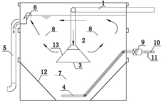
[0022] Such as figure 1 As shown, a radial flow sedimentation device includes a tank body (that is, a sedimentation tank), a central water inlet pipe 1, a water inlet bell mouth 2, a reflector 3, a mud collection pipe 4, an outlet pipe 5, an outlet weir 6, and a mud collection Bucket 7, coagulation sedimentation area 8, water pump 9, sludge return pipe 10, remaining sludge pipe 11, inclined plate 12, sludge discharge pipe, the central part of the sedimentation tank body is provided with a central water inlet pipe 1, and a central water inlet pipe The water outlet of 1 is located in the center of the pool body, the distance from the left and right sides of the pool body is 1.3 meters, and the distance from the bottom of the pool body is 1.5 meters. The water inlet end of the central water inlet pipe 1 is connected to the outlet pipe of the aerobic pool. The water outlet end of the central water inlet pipe 1 is connected to the water inlet bell mouth 2, and the reflection plate ...


PUM

PropertyMeasurementUnit
clearance rateaaaaaaaaaa

Abstract

The invention relates to a radial flow sedimentation device, which comprises a pool body, a mud discharge pipe, inclined plates, a water inlet pipe, a water outlet pipe, a water outlet weir, a sludge return pipe and a mud collecting bucket, the water outlet end of the water inlet pipe is located in the central part of the pool body, the water inlet end of the water inlet pipe is located above the water outlet end, the water outlet end of the water inlet pipe is connected with a horn mouth, a horizontally-placed reflecting board is hung just below the horn mouth, the inclined plates are respectively arranged at both sides of the lower part in the pool body, the sludge return pipe is arranged at the inner wall of an inclined plate close to one side, the water inlet end of the water inlet pipe is connected with the water outlet end of a sewage treatment pool arranged outside the pool body, the mud collecting bucket is enclosed by the two inclined plates at the bottom of the pool body, the mud inlet end of the sludge return pipe is inserted into the mud collecting bucket, and the bottom of the pool body is provided with a mud discharge port. The radial flow sedimentation device has the advantages of simple structure, low investment cost, small occupation area, and good precipitation effect, especially can effectively retain and separate suspended matters which are not easy to precipitate in the sewage, and can be widely used for various types of wastewater treatment systems high in water quality requirements.

Description

technical field [0001] The invention relates to a sedimentation technology in the field of water treatment equipment, in particular to a radial flow sedimentation device. Background technique [0002] In 1904, Americans Hazen and Camp invented the shallow pool settlement theory. On this basis, they successively developed inclined plate sedimentation tanks, inclined tube sedimentation tanks, interception sedimentation tanks, advection sedimentation tanks, etc., but the current application in the field of water treatment is Sedimentation tanks have certain disadvantages to varying degrees: 1. The design focus on sediment separation and efficient sludge discharge is different, and the function is single. When the water volume and water quality change, the impact resistance is poor; 2. The water flows through the inclined plate or inclined pipe. During the process, because the water flow is rising and the sediment is falling, it will cause relative motion to the settled suspende...

Claims


Application Information

Patent Timeline
Patent Type & Authority Patents(China)
IPC IPC(8): B01D21/02B01D21/24
Inventor 周少奇周晓黎强周娟
Owner SOUTH CHINA UNIV OF TECH
Learn More