A general-purpose drum bottom wall scrubbing device

A general-purpose, drum technology, applied in cleaning methods and utensils, cleaning hollow objects, chemical instruments and methods, etc., can solve problems such as low efficiency and labor consumption, and achieve convenient operation, improve brushing efficiency, and strong applicability. Effect

Active Publication Date: 2021-12-31
安徽省恒昌刷业有限公司
View PDF5 Cites 0 Cited by
  • Summary
  • Abstract
  • Description
  • Claims
  • Application Information

AI Technical Summary

Problems solved by technology

[0003] The purpose of the present invention is to solve the problems of labor-intensive and low efficiency in the prior art, and propose a general-purpose drum bottom wall scrubbing device

Method used


Image

  • A general-purpose drum bottom wall scrubbing device
  • A general-purpose drum bottom wall scrubbing device
  • A general-purpose drum bottom wall scrubbing device

Examples


Embodiment 1

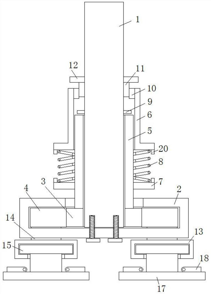
[0025] refer to Figure 1-4 , a general-purpose drum bottom wall scrubbing device, comprising a vertical control rod 1, the bottom of the vertical control rod 1 is provided with a bottom rectangular frame 2, the top side of the bottom rectangular frame 2 is provided with a top groove, and the two sides of the top groove The inner walls are respectively provided with side slide grooves, the bottom end of the vertical control rod 1 is fixedly connected with the inner wall of the top groove by bolts, and the outer rotation sleeve of the bottom end of the vertical control rod 1 is provided with a middle gear ring 3, and the two ends of the middle gear ring 3 The two tooth plates 4 are meshed and connected to the sides respectively, and the two tooth plates 4 are respectively slidably connected in the side chute, and the two ends of the tooth plates 4 respectively extend to the outside of the bottom rectangular frame 2, and the top end of the middle tooth ring 3 is fixedly connected...

Embodiment 2

[0029] Such as Figure 1-4 As shown, this embodiment is basically the same as Embodiment 1. Preferably, the two tooth plates 4 are arranged axisymmetrically with respect to the vertical central axis of the vertical control rod 1 .

[0030] In this embodiment, during adjustment, the rotation of the middle gear ring 3 can drive the gear plate 4 to move in the opposite direction, and the vertical control rod 1 is always located on the vertical central axis of the device.

Embodiment 3

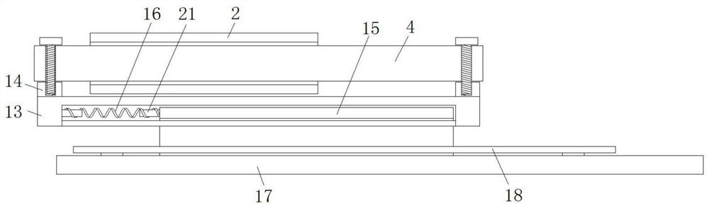
[0032] Such as Figure 1-4 As shown, this embodiment is basically the same as Embodiment 1. Preferably, the sides of the control cylinder 6 and the limit bottom ring 7 are fixedly connected with the spring positioning ring 20 respectively, and the two ends of the return spring 8 are respectively arranged on the spring Inside the positioning ring 20 , a spring positioning post 21 is fixedly connected to the vertical side of the slide plate 15 and the inner wall of one side of the horizontal chute, and the two ends of the booster spring 16 are respectively sleeved on the outside of the spring positioning post 21 .

[0033] In this embodiment, the arrangement of the spring positioning ring 20 and the spring positioning column 21 makes the return spring 8 and the booster spring 16 more stable during retraction and retraction.


PUM


Abstract

The invention discloses a general type drum bottom wall scrubbing device, which comprises a vertical control rod, the bottom of the vertical control rod is provided with a bottom rectangular frame, and the top side of the bottom rectangular frame is provided with a top groove, and the top groove The inner walls on both sides of the vertical control rod are provided with side chute respectively, and the bottom end of the vertical control rod is fixedly connected with the inner wall of the top groove by bolts. The two sides of the ring are respectively engaged with toothed plates, and the two toothed plates are respectively slidably connected in the side chute, and the two ends of the toothed plates respectively extend to the outside of the bottom rectangular frame, and the top end of the middle toothed ring is fixedly connected There is a connecting cylinder, the vertical outer wall of the connecting cylinder is a hexagonal structure, and the outer side of the connecting cylinder is fixedly connected with a limited bottom ring. The invention ensures the scrubbing effect of the inner wall and dead corners at the bottom of the drum, improves the scrubbing efficiency, has strong applicability, and is convenient to adjust, and meets the needs of people in production and life.

Description

technical field [0001] The invention relates to the technical field of scrubbing devices, in particular to a general-purpose scrubbing device for the bottom wall of a drum. Background technique [0002] Existing scrubbing equipment cannot fully scrub the dead angle between the cylinder inner wall and the vertical inner wall when scrubbing the inner wall of the bottom of the drum, resulting in poor scrubbing effect and labor-intensive, some disc-type brushes only It can only scrub the inner wall of the drum with a fixed size, and only the dead corners can be adjusted. It also needs to scrub the bottom plane of the drum. The operation is very inconvenient and cannot meet the needs of people in production and life. Contents of the invention [0003] The purpose of the present invention is to solve the problems of labor-intensive and low efficiency in the prior art, and propose a general-purpose drum bottom wall scrubbing device. [0004] In order to achieve the above object,...

Claims


Application Information

Patent Timeline
Patent Type & Authority Patents(China)
IPC IPC(8): B08B9/087
CPCB08B9/0808B08B9/0821
Inventor 汪晓林江小敏周明明
Owner 安徽省恒昌刷业有限公司
Why Eureka
Try Eureka