Engine cavity shell mold soil knocking hammer

A technology for knocking hammers and engines, which is applied in the field of mold soil removal tools for engine cavity shells. It can solve the problems of cavity shell impact, increasing the technical requirements of operators, and different levels of operating techniques, so as to increase the vibration speed and quickly Effect of stripping mold soil and improving separation efficiency

Active Publication Date: 2019-11-22
潍坊雷腾动力机械有限公司
View PDF5 Cites 0 Cited by
  • Summary
  • Abstract
  • Description
  • Claims
  • Application Information

AI Technical Summary

Problems solved by technology

[0010] Aiming at the deficiencies in the prior art, the present invention provides an engine cavity casing molding soil percussion hammer, which is used to solve the problem in the traditional technology of quickly separating the sand mold from the cavity casing, but ignoring the fact that each operator's operation Different technical heights have different effects on the cavity shell; when the sand mold is peeled off, it is easy to cause impact on the surface of the cavity shell; and limited by the irregular shape of the cavity shell, it makes it more difficult for the operator. Questions about technical requirements

Method used


Image

  • Engine cavity shell mold soil knocking hammer
  • Engine cavity shell mold soil knocking hammer
  • Engine cavity shell mold soil knocking hammer

Examples


Embodiment Construction

[0043]Embodiments of the technical solutions of the present invention will be described in detail below in conjunction with the accompanying drawings. The following examples are only used to illustrate the technical solutions of the present invention more clearly, and therefore are only examples, rather than limiting the protection scope of the present invention.

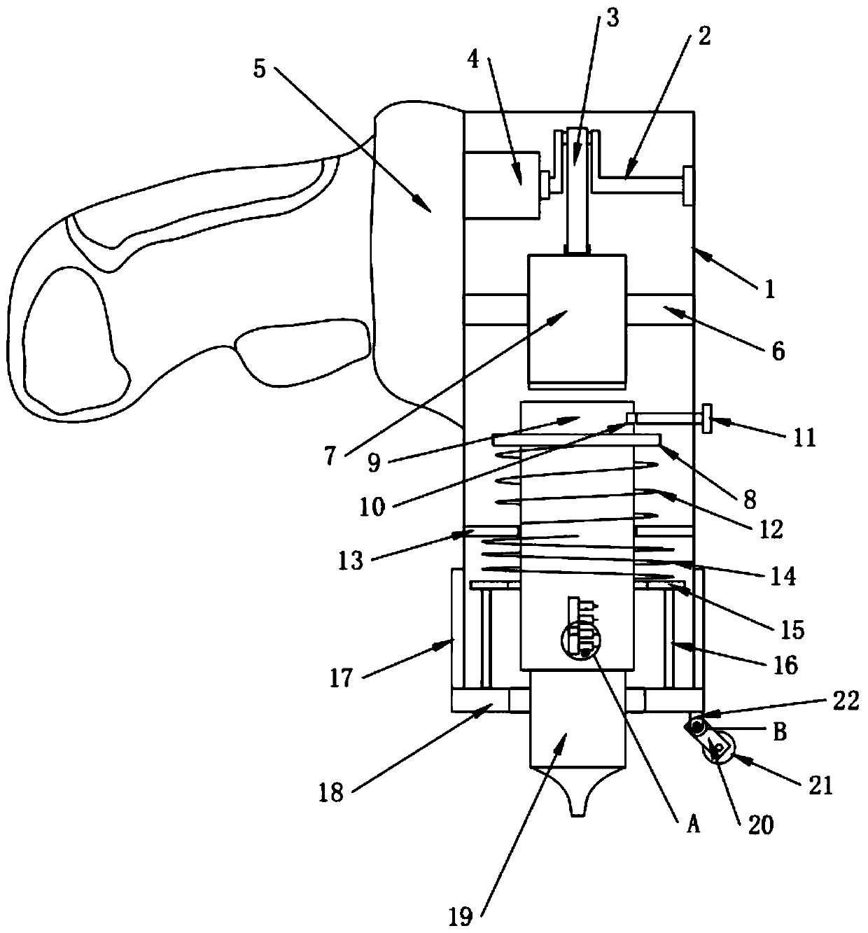
[0044] Such as Figure 1 to Figure 4 As shown, the engine cavity shell molding soil knocking hammer includes a cavity shell 1, and a knocking mechanism is installed on the cavity shell 1 to reciprocate and slide.

[0045] A control mechanism is also slidably installed on the chamber shell 1 to adjust its extension.

[0046] The control mechanism is also equipped with guide parts for guiding the movement and knocking.

[0047] A locking member for locking the striking mechanism is also installed on the cavity shell 1 .

[0048] The control mechanism is also provided with a control component for quantifying the amo...


PUM


Abstract

The invention discloses an engine cavity shell mold soil knocking hammer, and relates to the technical field of an engine cavity shell mold soil removal tool. The hammer comprises a cavity shell, anda knocking mechanism is arranged on the cavity shell in a reciprocated sliding manner. The problems that in the traditional technology, in order to enable a sand mold and a cavity shell to be rapidlyseparated, the different operation technology heights of operators are ignored, different influences on the cavity shell are caused, the influence that during sand mold stripping, the surface of the cavity shell is prone to be knocked is ignored, and due to limiting in irregularity of the cavity shell shape, the operator technical needs are increased are solved.

Description

technical field [0001] The invention relates to the technical field of tools for removing engine cavity shell mold soil, in particular to an engine cavity shell mold soil knocking hammer. Background technique [0002] An engine is a machine that can convert other forms of energy into mechanical energy, including internal combustion engines (gasoline engines, etc.), external combustion engines (Stirling engines, steam engines, etc.), electric motors, etc. For example, internal combustion engines usually convert chemical energy into mechanical energy. The engine is not only applicable to the power generating device, but also refers to the whole machine including the power device. [0003] The cavity shell of the engine is used as the carrier of the entire engine assembly. When the engine is produced, the relevant parts are assembled through the cavity shell. When the engine cavity shell is manufactured, most of them are casted. The raw material is poured into the sand mold f...

Claims


Application Information

Patent Timeline
Patent Type & Authority Applications(China)
IPC IPC(8): B22D29/08
CPCB22D29/08
Inventor 葛建厂
Owner 潍坊雷腾动力机械有限公司
Why Eureka
Try Eureka