Lattice compound shaft structure and construction method

A lattice type, wellbore technology, applied in wellbore lining, shaft equipment, earth-moving drilling, etc., can solve the problems of easy generation of cracks, hidden dangers of engineering quality, weak well wall strength, etc. The effect of hidden dangers of engineering quality

Active Publication Date: 2019-11-22
XIAN UNIV OF SCI & TECH
View PDF6 Cites 8 Cited by
  • Summary
  • Abstract
  • Description
  • Claims
  • Application Information

AI Technical Summary

Problems solved by technology

With the increase of the topsoil thickness, there is a problem that the well wall design is difficult to solve. Whether it is the design of the outer well wall or the inner well wall, when considering the frost heave pressure and the full water pressure design, the well wall thickness will be too large. Large or too high concrete strength grade
At the same time, at present, reinforced concrete is basically used as the shaft wall material for the support of shaft engineering, and steel mesh is generally bound, formwork is set up,

Method used


Image

  • Lattice compound shaft structure and construction method
  • Lattice compound shaft structure and construction method
  • Lattice compound shaft structure and construction method

Examples


Example Embodiment

[0044] Example 1

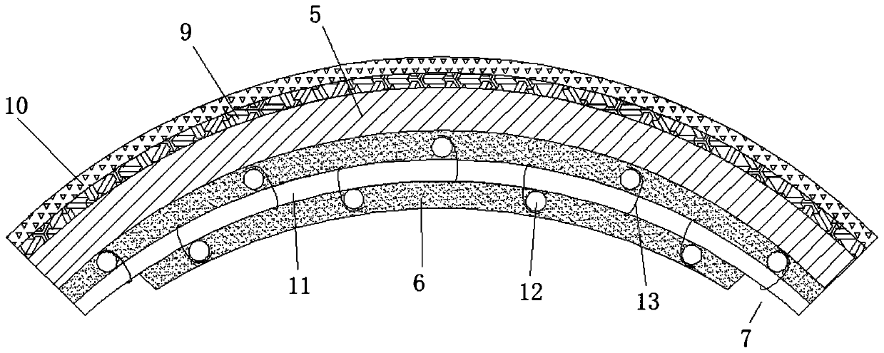
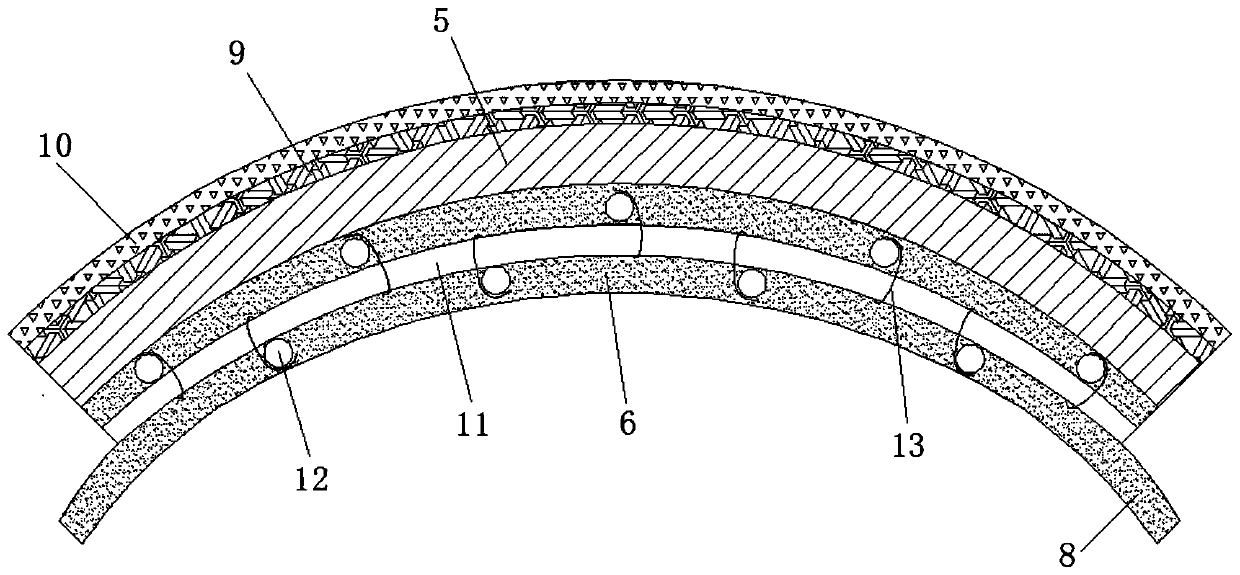
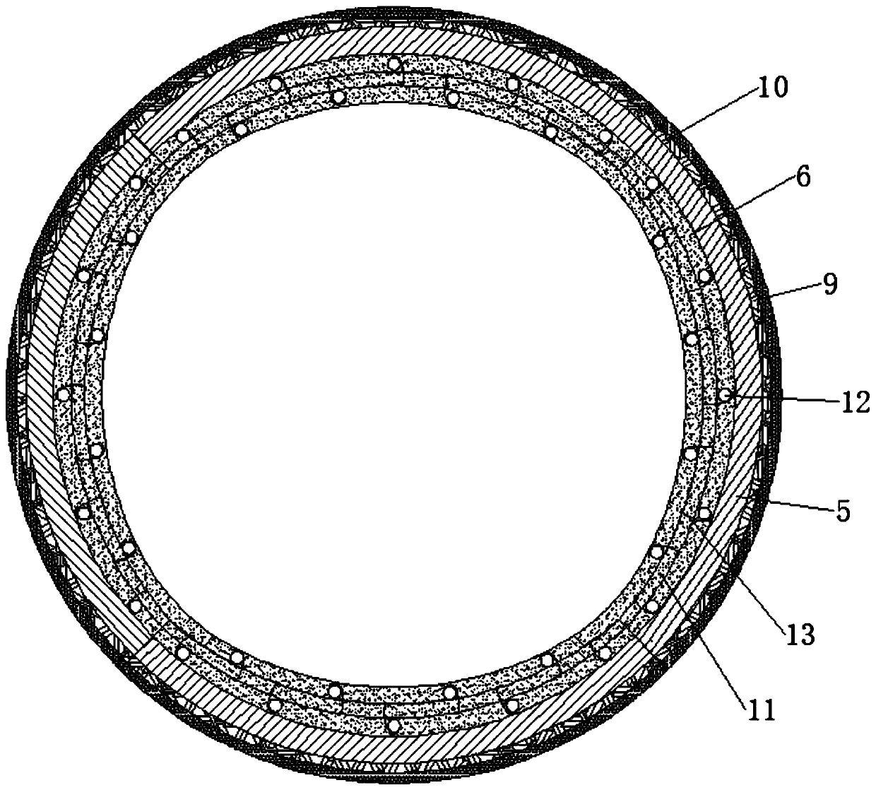
[0045] The invention provides a lattice type composite wellbore structure, specifically as follows Figure 1 to Figure 6 As shown, it includes an outer wellbore and an inner wellbore 1, the number of the outer wellbore is multiple, and the plurality of outer wellbores are connected in sequence from top to bottom. 1 is arranged in the outer wellbore and the outer wall and the inner wall of the outer wellbore are integrated by concrete; in this embodiment, the outer wellbore is prefabricated on a non-construction site, and after the prefabrication is completed, it is directly pulled to the construction site for hoisting, and the inner wellbore 1 is on the construction site. The construction is completed directly after hoisting the outer side of the outer shaft.

[0046] Specifically, the outer wellbore is composed of at least two first barrel walls 3 and two second barrel walls 4, and the first barrel walls 3 and the second barrel walls 4 are arranged at inte...

Example Embodiment

[0066] Example 2

[0067] like Figure 7 to Figure 9 As shown, in order to reduce the difficulty of hoisting, in this embodiment, at least four steel lattice columns 12 on the top and bottom of each outer wellbore extend outward to form the plug-in ends 14, and also include a plurality of crown beams 16, crown The top and bottom surfaces of the beam 16 are provided with at least four mounting holes 17 that are matched with the plug-in ends 14, and a crown beam 16 is provided between the upper and lower adjacent two outer wellbores. The end 14 and the mounting hole 17 are connected to the crown beam 16 , and the rest of the structure is the same as that of Embodiment 1, and will not be repeated here. The height of the crown beam 16 is lower than the height of the outer wellbore. During the hoisting process, the plug end 14 and the installation hole 17 are easier to quickly and accurately locate and plug each other, which improves the hoisting efficiency. At the same time, the ...


PUM


Abstract

The invention provides a lattice compound shaft structure and a construction method and relates to a coal mining technology. The lattice compound shaft structure comprises outer side shafts and an inner side shaft, the inner side shaft is arranged in the outer side shafts, and the outer wall of the inner side shaft is integrally connected with the inner walls of the outer side shafts through concrete. Each outer side shaft is composed of two first shaft walls and two second shaft walls which are sequentially surrounded and are arranged alternately. Each first shaft wall comprises a first steelmixed layer and a heat insulation plate arranged on the outer wall of the first steel mixed layer. Each second shaft wall comprises a second steel mixed layer and a heat insulation plate arranged onthe outer wall of the second steel mixed layer. Each of the first steel mixed layers and the second steel mixed layers comprises a structural steel framework and concrete poured to the periphery of the structural steel framework, the two ends of the interior of each first steel mixed layer contract inwards to form a limiting groove, and the two ends of the interior of each second steel mixed layerextend outwards to form a limiting block matched with the corresponding limiting groove. By means of the structure, the defects existing in an existing structure are overcome, damage caused by the earthquake action is effectively prevented, and the earthquake prevention and disaster reduction capability of coal mine shafts in China is improved.

Description

technical field [0001] The invention relates to coal mining technology, in particular to a lattice-type composite shaft structure and a construction method. Background technique [0002] With the rapid development of my country's economic construction, the demand for energy is increasing, and the problem of energy shortage is becoming more and more serious. It will take time for new energy to fully replace traditional energy. As far as my country's current energy composition is concerned, coal energy still occupies a dominant position. Therefore, building a new batch of large coal mines is an urgent task at present. [0003] However, with the depletion of shallow coal resources, excavating to the deep and building new mines in the deep surface soil will be an important problem to be solved urgently in coal mine construction. With the increase of topsoil thickness, there is a problem that the well wall design is difficult to solve. Whether it is the design of the outer well...

Claims


Application Information

Patent Timeline
IPC IPC(8): E21D5/11E21D5/12
CPCE21D5/11E21D5/12
Inventor 张程华
Owner XIAN UNIV OF SCI & TECH
Why Eureka
Try Eureka