

Gallery bridge wind load wind tunnel testing device by considering distance between bridge floor and water surface
A test device, wind load technology, applied in the direction of measuring device, machine/structural component test, aerodynamic test, etc., can solve the problem that the distance between bridge deck and water surface cannot be adjusted, and achieve simple installation and convenient use Effect
Active Publication Date: 2019-11-22
ZHEJIANG UNIV
View PDF10 Cites 2 Cited by
- Summary
- Abstract
- Description
- Claims
- Application Information
AI Technical Summary
Problems solved by technology
In the past, there was no research on the wind load of covered bridges considering different water surface heights (that is, different distances between the bridge deck and the water surface), mainly because the distance between the covered bridge deck and the water surface could not be adjusted in the test
Method used
View moreImage
Smart ImageViewing Examples

Examples
Embodiment
[0036] Now take a certain wind tunnel test device and test process as an example to illustrate the present invention.
Login to View More PUM
 Abstract
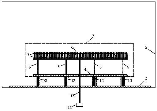
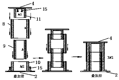
The invention discloses a gallery bridge wind load wind tunnel testing device by considering the distance between a bridge floor and a water surface. In a building wind tunnel, the upper end surface of a wind tunnel turntable is connected with the lower end surface of a gallery bridge floor model of a gallery bridge model through a plurality of connecting devices with the same structure, so that the distance between the gallery bridge floor model and the wind tunnel turntable is adjusted; the gallery bridge model is sequentially composed of a gallery bridge floor, a plurality of supporting gallery columns and an upper gallery pavilion model from bottom to top. A plurality of pressure measuring holes are formed in the outer surface of the upper gallery pavilion model and connected to an electronic scanning valve through pressure measuring hoses, and the wind pressure in the electronic scanning valve is collected to obtain the wind load of the gallery bridge; by adjusting the height of the connecting devices, the distances between different bridge floors and the water surface are tested; and through rotating the wind tunnel turntable, tests under different wind direction angles are achieved. According to the invention, different heights from the gallery bridge to the water surface can be simulated, the wind load of the gallery bridge at different heights is obtained, the influence of the gallery bridge and the water surface height on the gallery bridge wind load is analyzed, and a basis is provided for the wind-resistant design of the gallery bridge.
Description
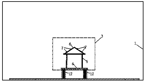
technical field [0001] The invention relates to a wind load test device, in particular to a bridge wind load wind tunnel test device considering the distance between the bridge deck and the water surface. Background technique [0002] In the construction of modern cities, in order to meet people's traffic and landscape requirements, modern corridor bridges have been built one after another. The modern covered bridge consists of the lower concrete bridge body, the middle supporting pillars, and the upper wooden pavilion. Figure 6 It is a typical form of modern covered bridges. The common feature of the upper gallery pavilions of modern covered bridges is that the same cross-section of the covered bridge usually has only two middle corridor columns in the lateral direction. In recent years, wind-induced collapses of pavilions on the upper part of modern covered bridges have occurred frequently, causing serious losses to people's lives and properties. [0003] For the wind lo...
Claims
Login to View More Application Information
Patent Timeline
 Patent Type & AuthorityApplications(China)
IPC IPC(8): G01M9/04G01M9/06
CPCG01M9/04G01M9/06
Inventor沈国辉张帅光陈勇包玉南李保珩赵英能
OwnerZHEJIANG UNIV