A heading error correction method for the initial segment of UAV tracking target based on dynamic inverse
A technology of heading error and target tracking, which is applied to the control of finding targets, navigation calculation tools, instruments, etc., and can solve problems such as time separation, system complexity, and implementation difficulties
- Summary
- Abstract
- Description
- Claims
- Application Information
AI Technical Summary
Problems solved by technology
Method used
Image
Examples
Embodiment 1
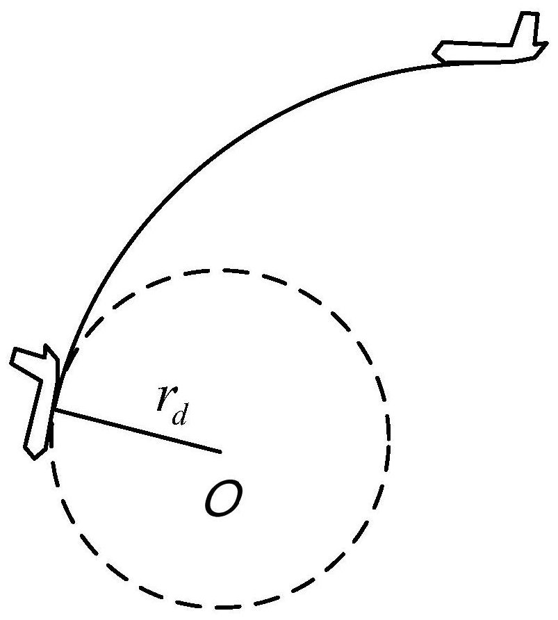
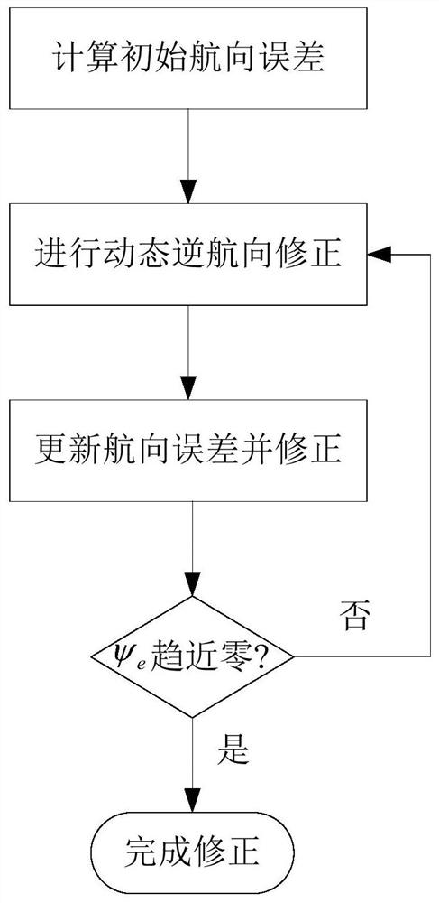
[0127] In this embodiment, the initial conditions for tracking and setting the simulation for the situation that the initial heading of the UAV is not aligned with the desired heading are: the target is at the origin (0,0); the initial position of the UAV is (6000m, 6000m); the initial position of the UAV is at (0,0); actual heading ψ 0 =π / 3; according to the Lyapunov vector field definition, the desired flight heading at the initial position of the UAV Then the initial heading error of the UAV tracking the target is In order to clearly represent the flight trajectory, this implementation sets the UAV flight speed u 0 =500m / s; the expected tracking radius is 2000m; the feasible error of heading error correction is 3%.
[0128] First, the Lyapunov vector field method is used to guide the UAV from the initial position along the vector field direction to the desired tracking trajectory of the target, such as Figure 5 shown.
[0129] The initial actual heading ψ of the UAV ...
Embodiment 2
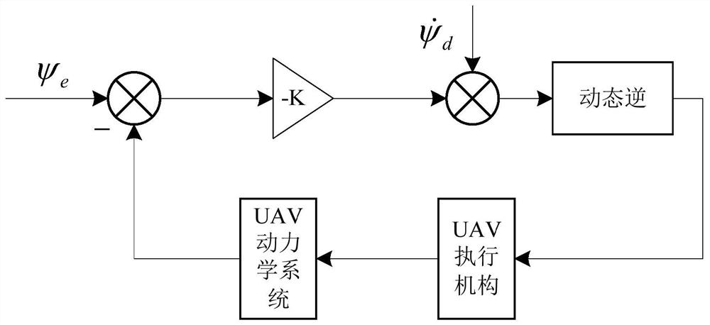
[0131] When the feedback gain k takes different values, the convergence speed of the heading error is also different. This embodiment is a simulation of the heading error convergence speed under different feedback gains k.
[0132] The simulation conditions of this example are the same as those of Example 1, but respectively k 1 =0.3, k 2 = 0.6 and k 3 = 2 to simulate, the simulation results are as follows Figure 8 shown. The schematic diagram of the heading error change under different feedback gains is as follows Figure 9 shown.
[0133] Table 1 Correction time under different k values
[0134]
[0135] Depend on Figure 8 and Figure 9 The simulation results show that as the value of the feedback gain k increases, the time required for the UAV to correct the heading error is less, that is, the UAV heading can quickly align with the desired direction of the guidance vector field.
[0136] It should be noted that the increase of the k value will also cause the U...
Embodiment 3
[0138] In this embodiment, the circular arc method is selected to correct the heading error of the initial section of the UAV, and a simulation comparison is made with the method of the present invention.
[0139] The specific method is to make the UAV fly along a circular trajectory when the UAV starts, and constantly compare the error between the UAV's current heading and the desired heading of the real-time position during the flight. Clearly, there is a point on the arc where the actual flight heading of the drone aligns with the desired heading of the Lyapunov vector field.
[0140] In order to compare the performance of the method of the present invention and the two heading error correction methods of the arc method, k=1 is taken in this embodiment, and the minimum turning radius of the UAV calculated under this curvature condition is r min = 206.9m. In order to ensure that the UAV can complete the correction of the heading error in the shortest time when the UAV adopt...
PUM
 Abstract
Description
Claims
Application Information
 - R&D
- Intellectual Property
- Life Sciences
- Materials
- Tech Scout
- Unparalleled Data Quality
- Higher Quality Content
- 60% Fewer Hallucinations
Browse by: Latest US Patents, China's latest patents, Technical Efficacy Thesaurus, Application Domain, Technology Topic, Popular Technical Reports.
© 2025 PatSnap. All rights reserved.Legal|Privacy policy|Modern Slavery Act Transparency Statement|Sitemap|About US| Contact US: help@patsnap.com


