
Power line carrier multi-level networking test system based on distributed noise injection and wireless connection

A power line carrier and test system technology, which is applied in the field of communication, can solve the problems of carrier signal crosstalk, cost increase, and limited hierarchical topology types, and achieve the effect of preventing cross-level conduction and preventing space coupling

Active Publication Date: 2020-12-29
BEIJING SMARTCHIP MICROELECTRONICS TECH COMPANY +2
View PDF8 Cites 0 Cited by
  • Summary
  • Abstract
  • Description
  • Claims
  • Application Information

AI Technical Summary

Problems solved by technology

[0006] However, the traditional power line carrier multi-level networking test system has the following two disadvantages: one is that the hierarchical topology types that can be constructed are limited, and the other is that the wired connection method is likely to cause carrier signal crosstalk, resulting in hierarchical confusion
The structure of the traditional power line carrier multi-level networking test system increases the cost of building the test environment and the space required. Due to the limitation of space and the number of shielding boxes, the test scale is generally limited to less than 300. This method is suitable for professional testing institutions. The test system is built, which is not suitable for the large-scale laboratory test environment in the research and development stage.

Method used


Image

  • Power line carrier multi-level networking test system based on distributed noise injection and wireless connection
  • Power line carrier multi-level networking test system based on distributed noise injection and wireless connection
  • Power line carrier multi-level networking test system based on distributed noise injection and wireless connection

Examples


Embodiment Construction

[0035] The specific embodiments of the present invention will be described in detail below in conjunction with the accompanying drawings, but it should be understood that the protection scope of the present invention is not limited by the specific embodiments.

[0036] Unless expressly stated otherwise, throughout the specification and claims, the term "comprise" or variations thereof such as "includes" or "includes" and the like will be understood to include the stated elements or constituents, and not Other elements or other components are not excluded.

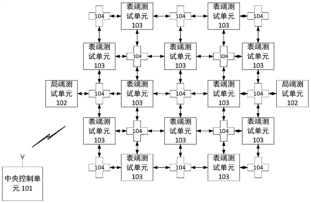
[0037] Such as figure 2 As shown, the power line carrier multi-level networking test system based on distributed noise injection and wireless connection according to the preferred embodiment of the present invention includes: a central control unit 101, a plurality of local end test units 102, and a plurality of meter end test units 103 And a plurality of routing attenuator networks 104, wherein the carrier test paths bet...


PUM


Abstract

The invention discloses a power line carrier multistage networking test system based on distributed noise injection and wireless connection. The system comprises a central control unit, a plurality oflocal side test units, a plurality of meter side test units and a plurality of routing attenuator networks. The system is characterized in that the central control unit communicates with each test unit and the plurality of routing attenuator networks. The local side test unit is used for testing local side tested carrier equipment. The local side tested carrier equipment in the carrier communication network is used as a central node of the network. The meter end testing unit is used for testing meter end tested carrier equipment and serves as a relay node or a terminal node of a network. Therouting attenuator networks are used as carrier communication routes of the local side test units and the meter side test units. Each routing attenuator network can be connected with a plurality of test units; wherein each of the plurality of local side test units and the plurality of meter side test units is internally provided with a noise injection module. The noise injection module is coupledto a carrier interface of tested carrier equipment of the test unit.

Description

technical field [0001] The invention relates to the technical field of communication, in particular to a power line carrier multi-stage networking test system based on distributed noise injection and wireless connection. Background technique [0002] Low-voltage power line broadband carrier (LVPLC) communication is a special communication method that uses low-voltage power distribution lines (380 / 220V subscriber lines) as information transmission media for voice or data transmission. This technology is to load the high-frequency signal carrying information on the current, and then use various levels of power line transmission, and the modem receiving the information separates the high-frequency signal from the current and transmits it to the power line broadband user terminal (computer, TV) Or telephone and smart meter, switch, changer). This technology realizes the bearing of multiple services such as data, voice and video on the existing wires without rewiring. Generally...

Claims


Application Information

Patent Timeline
Patent Type & Authority Patents(China)
IPC IPC(8): H04L12/24H04W24/02H04W24/06H04W40/22H04B3/54
CPCH04B3/544H04L41/044H04L41/0803H04L41/12H04W24/02H04W24/06H04W40/22
Inventor 郝伟琦王贤辉赵东艳王于波肖德勇李铮秦亮亮陈奎熹王辰皓
Owner BEIJING SMARTCHIP MICROELECTRONICS TECH COMPANY
Learn More