Projection device and lens

A technology of projection equipment and lens, which is applied in the field of projection, can solve the problems of low imaging quality of projection equipment and lens, achieve the best projection quality, improve imaging quality, and realize the effect of precise adjustment

Inactive Publication Date: 2019-11-29
QINGDAO HISENSE LASER DISPLAY CO LTD
View PDF16 Cites 4 Cited by
  • Summary
  • Abstract
  • Description
  • Claims
  • Application Information

AI Technical Summary

Problems solved by technology

[0004] The application provides a projection device and a lens, which can solve the

Method used


Image

  • Projection device and lens
  • Projection device and lens
  • Projection device and lens

Examples


Embodiment Construction

[0039] In order to make the purpose, technical solution and advantages of the present application clearer, the implementation manners of the present application will be further described in detail below in conjunction with the accompanying drawings.

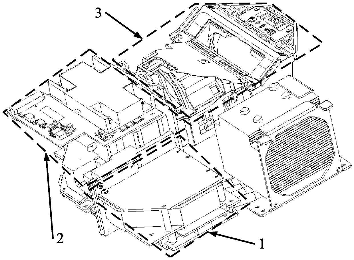
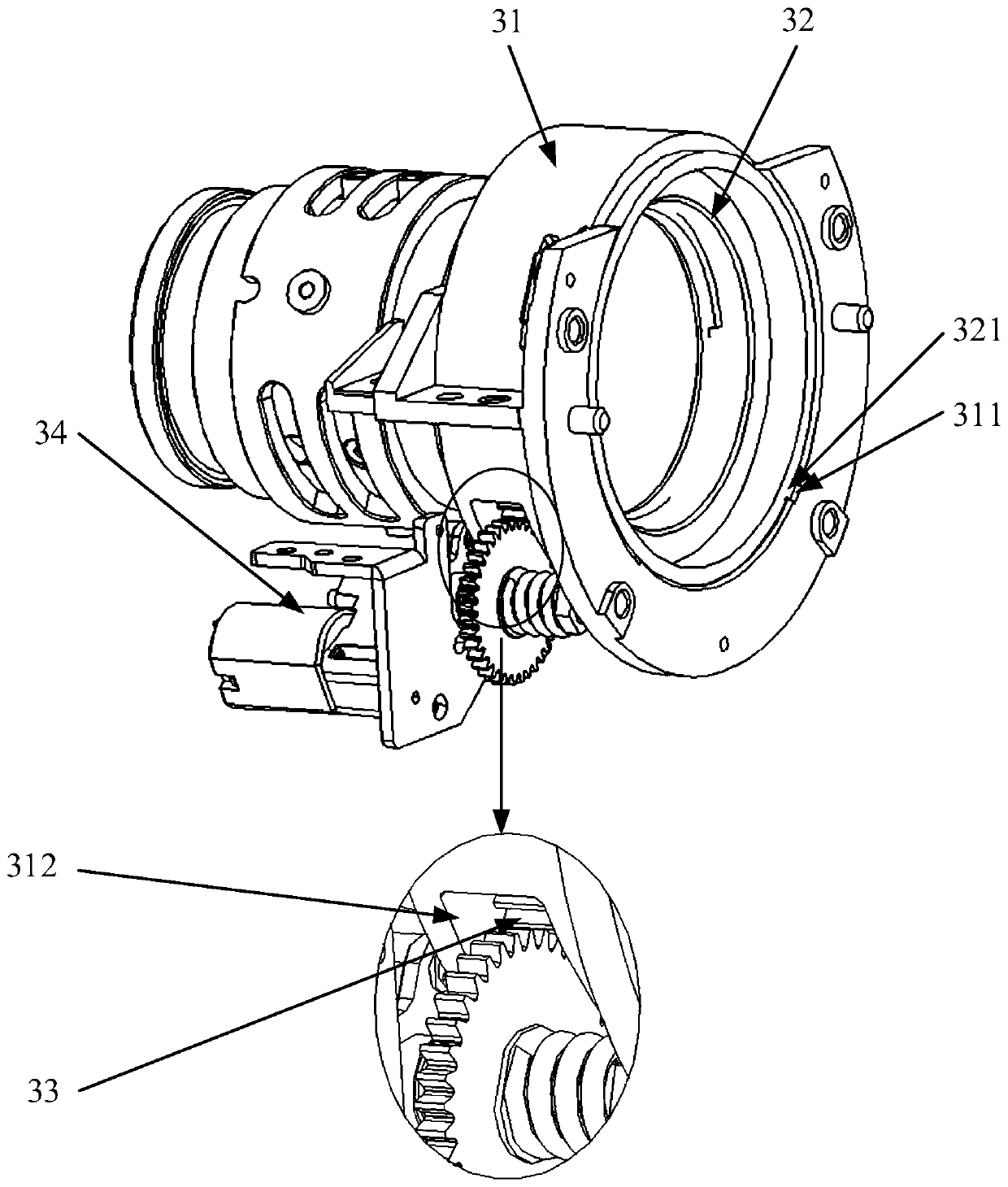
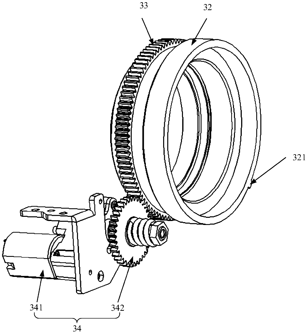
[0040] figure 1 A schematic structural diagram illustrating a projection device according to an embodiment of the present application, figure 2 A schematic structural diagram of a lens according to an embodiment of the present application is illustrated. Such as figure 1 and figure 2 As shown, the projection device includes: a light source 1; an optical-mechanical system 2, the optical-mechanical system 2 is connected to the light source 1; a lens 3, including a main lens barrel 31, a middle group lens barrel 32, a gear ring 33, a driving mechanism 34 and a controller 35; the first end of the main lens barrel 31 is connected to the optomechanical system 2, the gear ring 33 is limited in the inner cavity of the second end of ...


PUM


Abstract

The application discloses a projection device and a lens, belonging to the technical field of projection. The projection device includes a light source, an optical-mechanical system, and a lens; the optical-mechanical system is connected to the light source; the lens includes a main lens barrel, a middle group lens barrel, a gear ring, a driving mechanism and a controller; the gear ring is limitedin an inner cavity of a second end of the main lens barrel and can rotate relative to the circumferential direction of the main lens barrel; the inner wall of the second end of the main lens barrel is provided with a guide groove extending in the axial direction; the outer wall of the middle group lens barrel is provided with a boss; one end of the middle group lens barrel extends into the innercavity of the second end of the main lens barrel and is connected to the gear ring in a threaded manner; the boss is clamped in the guide groove; the driving mechanism is fixed on the outer wall of the main lens barrel; the controller is electrically connected to the driving mechanism; and the driving mechanism can drive the gear ring to rotate based on the controller. According to the application, the driving mechanism is controlled by the controller, so as to drive the gear ring to rotate, and finally realize the adjustment of the middle group lens barrel, so that the precise adjustment of the focal length is realized, which has the effect of improving the imaging quality of the projection device.

Description

technical field [0001] The present application relates to the field of projection technology, in particular to a projection device and a lens. Background technique [0002] A projection device is a display device for generating projected images. At present, the projection device mainly includes an optical engine and a lens. The optical engine is used to modulate the light beam provided by itself, and sends the modulated light beam to the lens. The lens is used to perform imaging based on the light beam modulated by the optical engine. Since the lens is an important part of the imaging of the projection device, when the imaging is performed through the lens, if the precision components included in the lens change direction or deviate in position, it is easy to cause the imaging picture to appear blurred or out of focus. At this time, the imaging picture can be adjusted through the focusing function of the lens, so as to improve the quality of the projected picture of the pro...

Claims


Application Information

Patent Timeline
IPC IPC(8): G02B7/09G02B7/10G03B21/53
CPCG02B7/09G02B7/102G03B21/53
Inventor 李建军钟强董淑斌黄永达
Owner QINGDAO HISENSE LASER DISPLAY CO LTD
Why Eureka
Try Eureka