Sweeping robot

A technology of a sweeping robot and a robot body, applied in the field of sweeping robots, can solve problems such as troublesome replacement

Pending Publication Date: 2019-12-03
高殷沛
View PDF0 Cites 0 Cited by
  • Summary
  • Abstract
  • Description
  • Claims
  • Application Information

AI Technical Summary

Problems solved by technology

[0003] Then, the brushes used in these current sweeping machines are all embedded in the shell of the robot, and only part of the bristles are exposed outside. When the brush needs to be removed, the bottom baffle screw needs to be unscrewed, and then extended into The brush can only be removed from the inside of the shell, and it is very troublesome to replace

Method used


Image

  • Sweeping robot
  • Sweeping robot
  • Sweeping robot

Examples


Embodiment 1

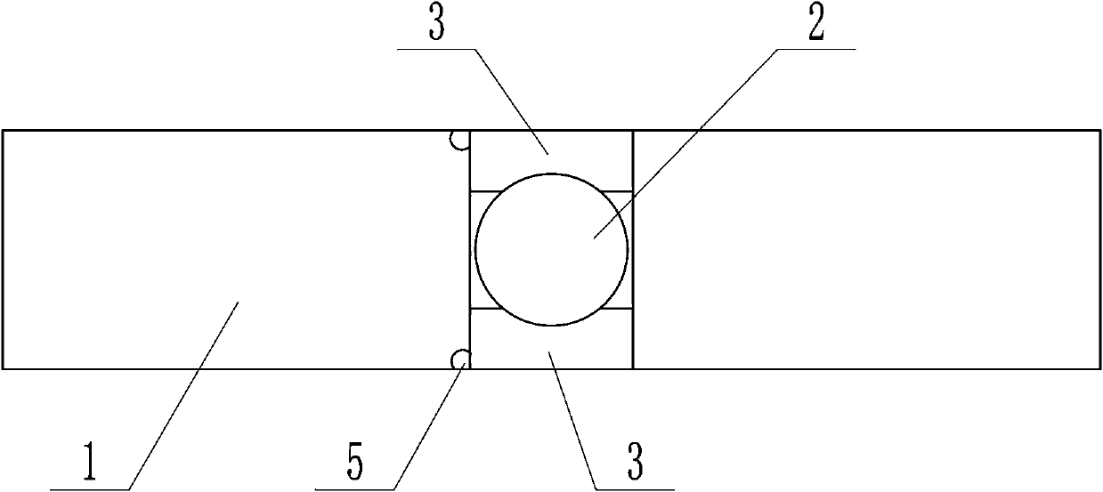
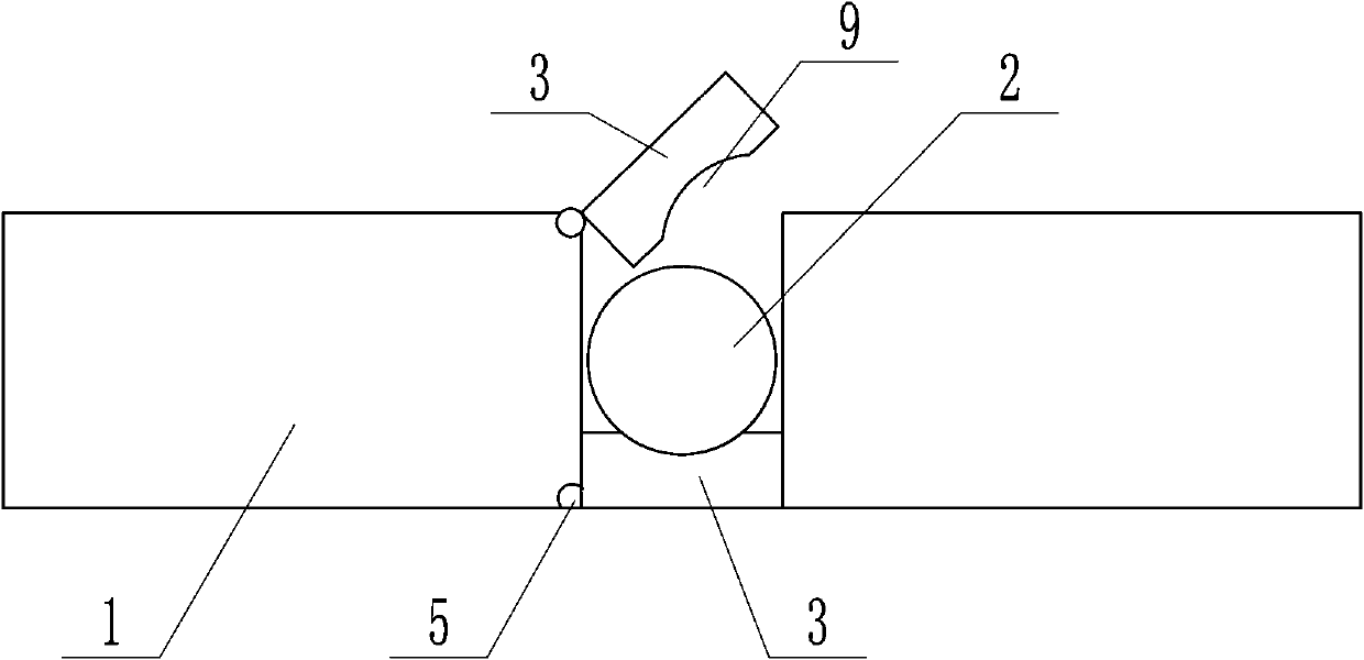
[0021] as attached figure 1 , 2 As shown, the present invention includes a robot body and a brush 2 arranged at the bottom of the robot body. It should also have a walking wheel (not shown in the figure), and the brush 2 is connected to the drive motor. Except for the connection form between them, other structures are the same as those of the existing sweeping robot. The brush 2 includes a central shaft and bristles arranged on the outer wall of the central shaft. The matching structure between the brush 2 and other components mentioned in the present invention refers to the cooperation of the central shaft.

[0022] The two ends of the central axis of the brush 2 respectively expose the side walls of the housing 1, and the central axis of the brush 2 is connected to the housing 1 through a movable connection device, so that the brush 2 can be blocked from the outside to be unloaded. Down.

[0023] The movable connection device includes a clamping plate 3 arranged on one si...

Embodiment 2

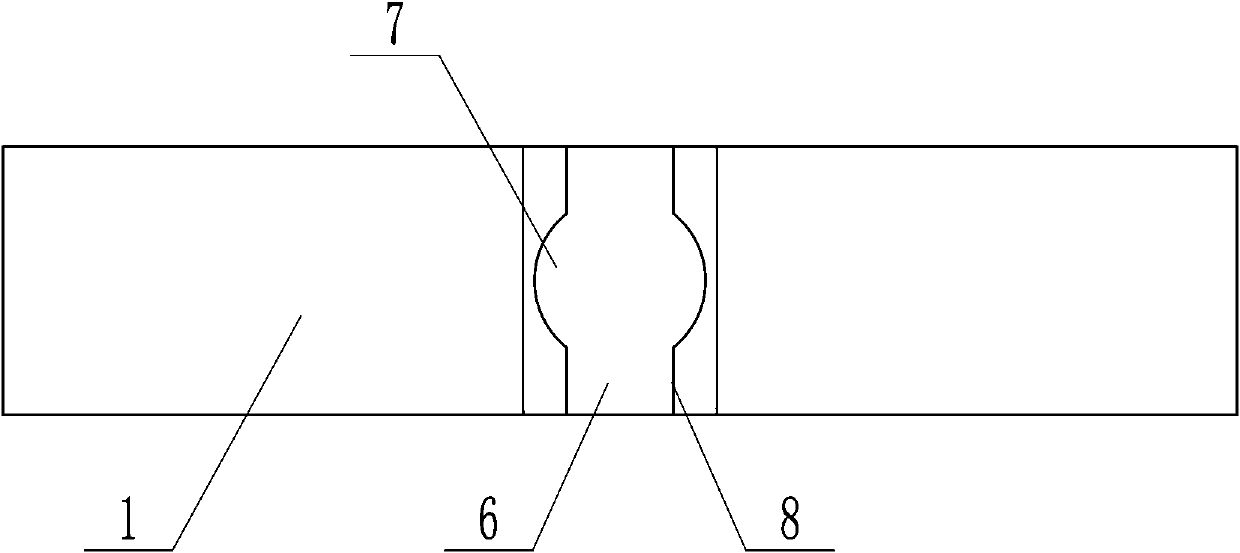
[0028] as attached image 3 As shown, on the basis of Embodiment 1, other structures are kept unchanged, and only the structure of the movable connection device is changed.

[0029] In this embodiment, the movable connection device includes an installation hole 7 correspondingly arranged on the side wall of the housing 1 and a clamping channel 6 arranged at the upper end and / or lower end of the installation hole 7, the installation hole 7 and the brush 2 The two ends correspond to each other, the inner diameter of the clamping channel 6 is smaller than the outer diameter of the two ends of the central axis of the brush 2, and the left and right side walls 8 of the clamping channel 6 are made of elastic material with elasticity, which is used to make the brush 2 Both ends of the brush 2 snap into the mounting hole 7 .

[0030] Due to the elasticity of the channel side wall 8, when the brush 2 is inserted in or taken out, the channel side wall 8 is pressed and moves outward to ...


PUM


Abstract

The invention relates to a sweeping robot which comprises a robot body and a brush arranged at the bottom of the robot body. The two ends of the brush are exposed out of the two ends of a shell of therobot body respectively, so that the brush can be clamped from the two ends to be detached. The brush is connected with the shell of the robot body through a movable connecting device, the two ends of the brush are exposed out of the side wall of the shell, and meanwhile, the movable connecting device is connected with the shell. When the brush needs to be detached, only the movable connecting device needs to be opened, and then the two ends of the brush are grabbed or clamped from the outer side of the side wall of the shell, so that the brush is moved upwards or downwards to be detached, and the brush replacing and washing work is easier and more convenient.

Description

technical field [0001] The invention relates to the field of smart home appliances, in particular to a sweeping robot. Background technique [0002] The original intention of the cleaning robot design is to replace humans to do heavy cleaning tasks. Most of the cleaning robots currently on the market have structures such as brushes, water tanks, and moving rollers. The brushes are used to suck the dust on the bottom surface into the dust box inside the robot. At the same time, the water from the water tank can be used to mop the floor. [0003] Then, the brushes used in these current sweeping machines are all embedded in the shell of the robot, and only part of the bristles are exposed outside. When the brush needs to be removed, the bottom baffle screw needs to be unscrewed, and then extended into The brush cannot be removed until it is inside the housing, and it is very troublesome to replace. Contents of the invention [0004] The technical problem to be solved by the...

Claims


Application Information

Patent Timeline
IPC IPC(8): A47L11/24A47L11/40
CPCA47L11/24A47L11/4083A47L11/40
Inventor 高殷沛
Owner 高殷沛
Why Eureka
Try Eureka