Oil drum label silk-screen printing equipment
An oil drum and label technology, applied in screen printing machines, printing, printing machines and other directions, can solve the problems of easy human error, low technical requirements of workers, and low error rate in the screen printing process, and achieves the goal of reducing difficulty and improving work efficiency. Effect
- Summary
- Abstract
- Description
- Claims
- Application Information
AI Technical Summary
Problems solved by technology
Method used
Image

Examples
Embodiment approach 1
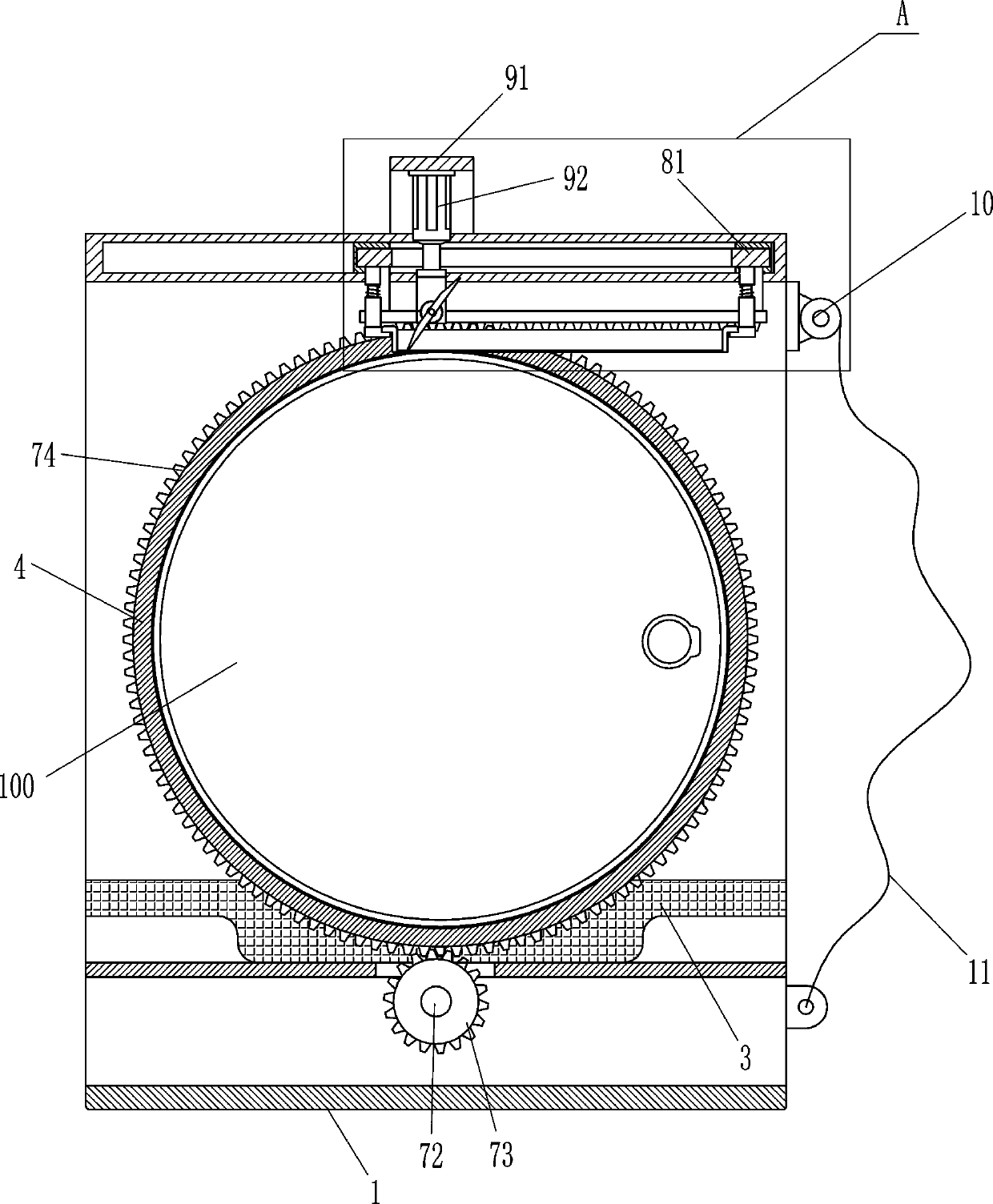
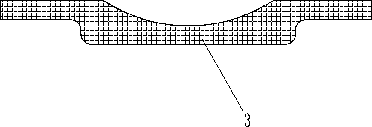
[0021] An oil barrel label screen printing equipment, such as figure 1 with figure 2 As shown, it includes a U-shaped frame 1, a horizontal plate 2 and a support seat 3. The lower part of the inner side of the U-shaped frame 1 is connected with a horizontal plate 2, and the horizontal plate 2 is connected to the U-shaped frame 1 by bolts. The horizontal plate 2 The top is provided with a support seat 3 for placing the oil drum 100, and also includes a chuck 4, a mounting frame 5, a hydraulic cylinder 6 and a rotating mechanism 7, and the U-shaped frame 1 is equipped with chucks in the middle of the left and right sides. 4. There is a mounting frame 5 on the right outside of the U-shaped frame 1. The mounting frame 5 is connected to the outside of the U-shaped frame 1 by bolts. The hydraulic cylinder 6 is installed on the mounting frame 5. The hydraulic cylinder 6 is connected by bolts. Connected with the mounting frame 5, the telescopic rod of the hydraulic cylinder 6 is rot...
Embodiment approach 2
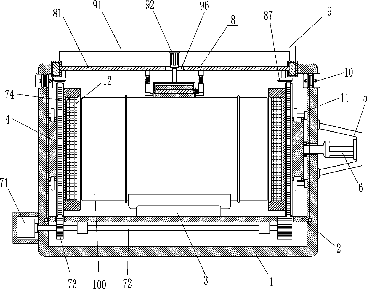
[0026] Such as figure 1 , image 3 with Figure 5 As shown, a synchronous movement mechanism 8 is also included, and the synchronous movement mechanism 8 includes a mobile plate 81, a guide rod 82, a conduit 83, an elastic member 84, a fixed seat 85 and a rack 87, between the two ends of the U-shaped frame 1 top. Slidingly connected with a moving plate 81, the left and right sides of the bottom of the moving plate 81 are provided with guide rods 82, the guide rods 82 are connected with the moving plate 81 by welding, the outside of the guide rod 82 is slidably provided with a conduit 83, and the conduit 83 is connected to the movable plate 81. An elastic member 84 is connected between the guide rods 82, and a fixed seat 85 is connected between the bottoms of the two conduits 83. The fixed seat 85 is connected to the bottom of the conduits 83 by welding. The fixed seat 85 is used to place the silk screen for printing the oil drum 100 The mesh plate 200 and the left and right ...
Embodiment approach 3
[0031] Such as figure 1 As shown, it also includes a winch 10 and a wire rope 11. Both sides of the U-shaped frame 1 front side upper part are equipped with a winch 10, and the hoist 10 is connected with the U-shaped frame 1 by bolts, and the hoist 10 is wound with a wire rope. 11. The tail end of the steel wire rope 11 is fixed on the lower part of the front side of the U-shaped frame 1.
[0032] When the oil drum 100 needs to be placed on the support base 3, the oil drum 100 can be placed on the front side of the U-shaped frame 1 first, and the steel wire rope 11 is wound around the outer surface of the oil drum 100, and then the hoist 10 is started to retract the steel wire rope 11 , the wire rope 11 is retracted and the oil drum 100 is brought into the U-shaped frame 1, so that the oil drum 100 is not manually put into the support seat 3.
[0033] Such as figure 1 As shown, an electromagnet 12 is also included, the chuck 4 is provided with an electromagnet 12, and the el...
PUM
 Abstract
Description
Claims
Application Information
 - R&D
- Intellectual Property
- Life Sciences
- Materials
- Tech Scout
- Unparalleled Data Quality
- Higher Quality Content
- 60% Fewer Hallucinations
Browse by: Latest US Patents, China's latest patents, Technical Efficacy Thesaurus, Application Domain, Technology Topic, Popular Technical Reports.
© 2025 PatSnap. All rights reserved.Legal|Privacy policy|Modern Slavery Act Transparency Statement|Sitemap|About US| Contact US: help@patsnap.com