

Shoe main heel grinding equipment for leather shoe processing
A shoe and taproot technology, applied in metal processing equipment, grinding/polishing equipment, applications, etc., can solve the problems of inability to adjust the grinding wheel and inconvenient use by shoemakers
- Summary
- Abstract
- Description
- Claims
- Application Information
AI Technical Summary
Problems solved by technology
Method used
Image

Examples
Embodiment 1
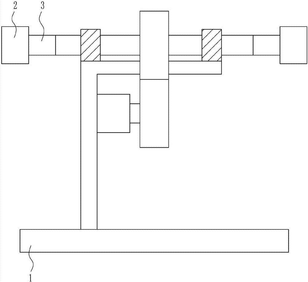
[0043] A shoe main root grinding equipment for leather shoe processing, such as Figure 1-8 As shown, it includes a base plate 1 , a grinding device 2 and a clamping device 3 , the grinding device 2 is provided on the top of the base plate 1 , and the clamping device 3 is installed on the grinding device 2 .
Embodiment 2
[0045] A shoe main root grinding equipment for leather shoe processing, such as Figure 1-8 As shown, it includes a base plate 1 , a grinding device 2 and a clamping device 3 , the grinding device 2 is provided on the top of the base plate 1 , and the clamping device 3 is installed on the grinding device 2 .
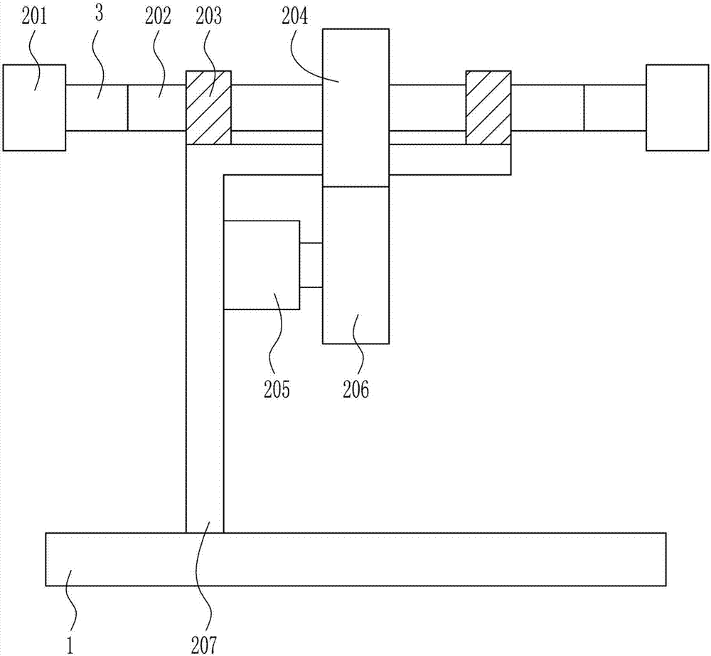
[0046] The grinding device 2 includes a grinding wheel 201, a first rotating shaft 202, a bearing seat 203, a first gear 204, a first motor 205, a second gear 206 and a support 207, the bottom plate 1 top is provided with a support 207, and the bottom right side of the support 207 is provided with There is a first motor 205, the right side of the first motor 205 is provided with a second gear 206, the left and right sides of the top of the bracket 207 are provided with bearing seats 203, and the first rotating shaft 202 is connected between the bearing seats 203 on the left and right sides, and the second A rotating shaft 202 passes through the bearing seats 203 on the l...
Embodiment 3
[0048] A shoe main root grinding equipment for leather shoe processing, such as Figure 1-8 As shown, it includes a base plate 1 , a grinding device 2 and a clamping device 3 , the grinding device 2 is provided on the top of the base plate 1 , and the clamping device 3 is installed on the grinding device 2 .
[0049] The grinding device 2 includes a grinding wheel 201, a first rotating shaft 202, a bearing seat 203, a first gear 204, a first motor 205, a second gear 206 and a support 207, the bottom plate 1 top is provided with a support 207, and the bottom right side of the support 207 is provided with There is a first motor 205, the right side of the first motor 205 is provided with a second gear 206, the left and right sides of the top of the bracket 207 are provided with bearing seats 203, and the first rotating shaft 202 is connected between the bearing seats 203 on the left and right sides, and the second A rotating shaft 202 passes through the bearing seats 203 on the l...
PUM
 Abstract
Description
Claims
Application Information