
Tray

A pallet and plate body technology, applied in the field of article supporting devices, can solve the problems of easily damaged ground, uneven surface of the pallet, affecting the stability of the goods placed on the pallet, etc. effect of risk

Active Publication Date: 2019-12-03
瑞迹工业技术(上海)有限公司
View PDF6 Cites 2 Cited by
  • Summary
  • Abstract
  • Description
  • Claims
  • Application Information

AI Technical Summary

Problems solved by technology

For example, for a pallet with outriggers, the contact area between the outriggers and the ground is small, and the ground at the position of the outriggers of the pallet is under greater pressure, the ground is easy to be damaged, and the pallet outriggers are also easy to sink into the ground, resulting in uneven surface of the pallet. Level, which affects the stability of the goods placed on the pallet

Method used


Image

  • Tray
  • Tray
  • Tray

Examples


Embodiment 1

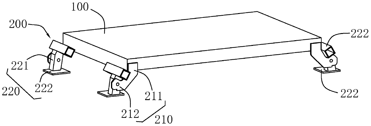
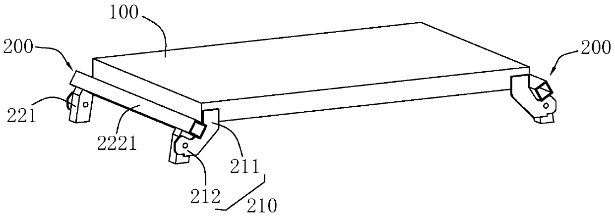
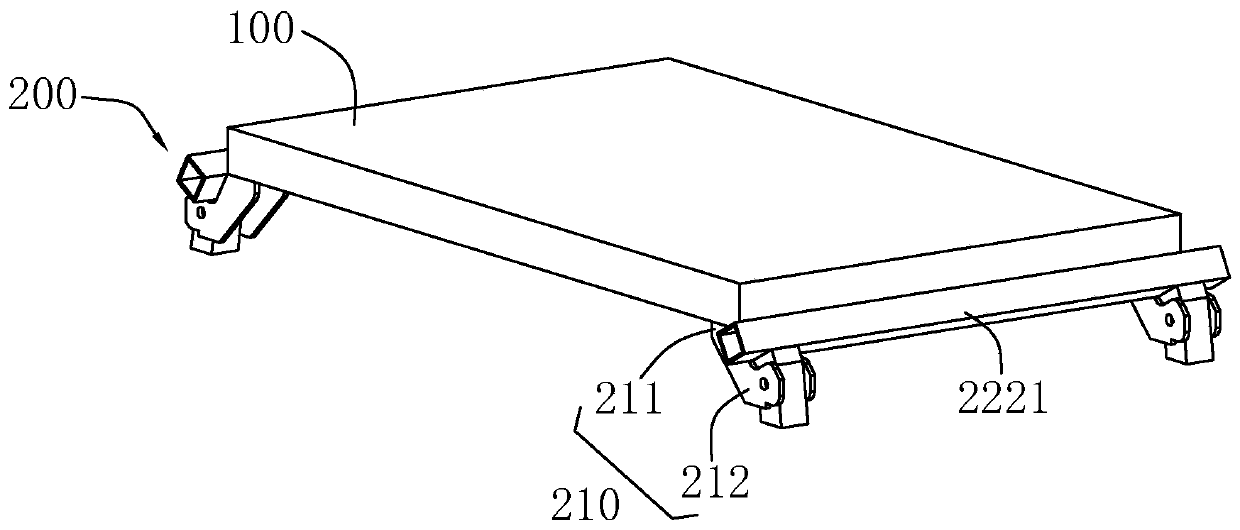
[0054] a tray such as figure 1 As shown, the tray body 100 is included, and the tray body 100 is provided with a tray support structure 200 for changing the bearing area between the tray body 100 and the external receiving surface.

[0055] like figure 1 As shown, the pallet supporting structure 200 includes a connecting portion 210 and a supporting portion 220 .

[0056] The connecting part 210 is configured to be fixedly connected to the tray body 100 , and the supporting part 220 is configured to be movably connected to the connecting part 210 for providing at least two supporting surfaces with different contact areas with the external receiving surface.

[0057] A state switching mechanism is provided between the connecting portion 210 and the supporting portion 220 to change the contact area between the supporting portion 220 and the external receiving surface.

[0058] detailed, such as figure 1 and figure 2 As shown, the tray body 100 is preferably arranged in a rect...

Embodiment 2

[0068] a tray such as Figure 5 and Image 6 As shown, the difference from Embodiment 1 is that the connection part 210 includes legs 213 arranged at the four corners of the tray body 100, the legs 213 are arranged perpendicular to the tray body 100, and the bottom of the legs 213 is provided with a soft Cushion. The supporting part 220 includes a cross bar 223 arranged between two adjacent legs 213 or between the legs 213 on the same side of the tray body 100 . Hinged with the leg 213 , the rotation plane of the connecting rod 224 is parallel to the height direction of the tray body 100 . In order to ensure that the rotation of the cross bar 223 will not be interfered by the legs 213, the length of the connecting rod 224 is not less than the length of the legs 213, that is, after the connecting rod 224 rotates, the maximum distance between the surface of the cross bar 223 and the tray body 100 is greater than The distance between the ends of the legs 213 and the tray body ...

Embodiment 3

[0076] a tray such as Figure 7 and Figure 8 As shown, the difference from the second embodiment is that: the outrigger 213 is provided with a storage groove 2135 along its length direction, the connecting rod 224 is stored in the accommodating groove 2135, and the above-mentioned connecting rod 224 and the outrigger 213 are connected by a lock. Pin 2241 realizes locking and disengagement.

[0077] Preferably, the legs 213 are arranged in an arc shape on one side facing the tray body 100, so as to facilitate stacking between two adjacent trays.


PUM


Abstract

The invention discloses a tray, and relates to the technical field of article supporting devices, the tray comprises a tray body, and the tray body is provided with a tray supporting structure used for changing the force bearing area between the tray body and an external bearing surface; the tray supporting structure comprises a connecting part which is fixedly connected with the tray body, and comprises a supporting part, the supporting part is configured to be movably connected with the connecting part and is used for providing at least two supporting surfaces with different contact areas with an external bearing surface; a state switching mechanism is arranged between the connecting part and the supporting part and used for changing the contact area between the supporting part and an external bearing surface. Through the arrangement of the tray supporting structure, when the tray is used, the contact area between the tray and a bearing surface, such as the ground, can be flexibly adjusted according to use requirements, and then the pressure intensity between the tray and the bearing surface and the placement stability are adjusted, so that the tray can adapt to different places.

Description

technical field [0001] The present invention relates to the technical field of article supporting devices, more specifically, it relates to a tray. Background technique [0002] Pallet is a common device used to support goods in daily life, which is convenient for the placement and handling of goods. [0003] Existing cargo pallets usually include a pallet body and outriggers. In order to facilitate stacking of the pallets, the above outriggers are usually realized by protruding from the bottom of the pallet or directly omitted. The above setting has many problems in some specific usage environments. For example, for a pallet with outriggers, the contact area between the outriggers and the ground is small, and the ground at the position of the outriggers of the pallet is under greater pressure, the ground is easy to be damaged, and the pallet outriggers are also easy to sink into the ground, resulting in uneven surface of the pallet. The level affects the stability of the ...

Claims


Application Information

Patent Timeline
Patent Type & Authority Applications(China)
IPC IPC(8): B65D19/40
CPCB65D19/40
Inventor 叶斐叶政龚永平
Owner 瑞迹工业技术(上海)有限公司
Learn More