Powerful switching valve

A switching valve, powerful technology, applied in valve details, multi-port valves, valve devices, etc., can solve problems such as insufficient suction, and achieve the effect of improving production and conveying efficiency

Pending Publication Date: 2019-12-03
苏州希瑞格机器人科技有限公司
View PDF0 Cites 0 Cited by
  • Summary
  • Abstract
  • Description
  • Claims
  • Application Information

AI Technical Summary

Problems solved by technology

[0004] The purpose of the present invention is to provide a powerful switching valve to solve the problem that the suction force of the switching valve is not strong enough when sucking up hollow products with empty ends in the above-mentioned background technology

Method used


Image

  • Powerful switching valve
  • Powerful switching valve
  • Powerful switching valve

Examples


Embodiment Construction

[0022] The following will clearly and completely describe the technical solutions in the embodiments of the present invention with reference to the accompanying drawings in the embodiments of the present invention. Obviously, the described embodiments are only some, not all, embodiments of the present invention. Based on the embodiments of the present invention, all other embodiments obtained by persons of ordinary skill in the art without making creative efforts belong to the protection scope of the present invention.

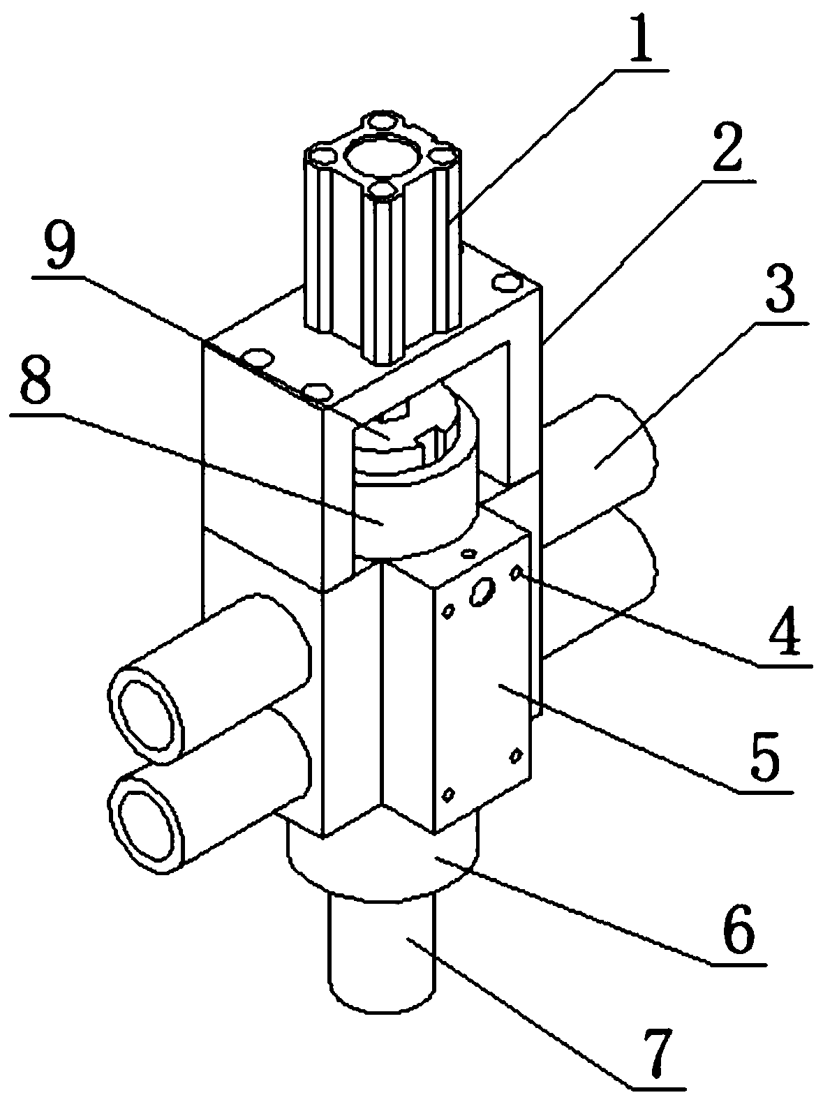
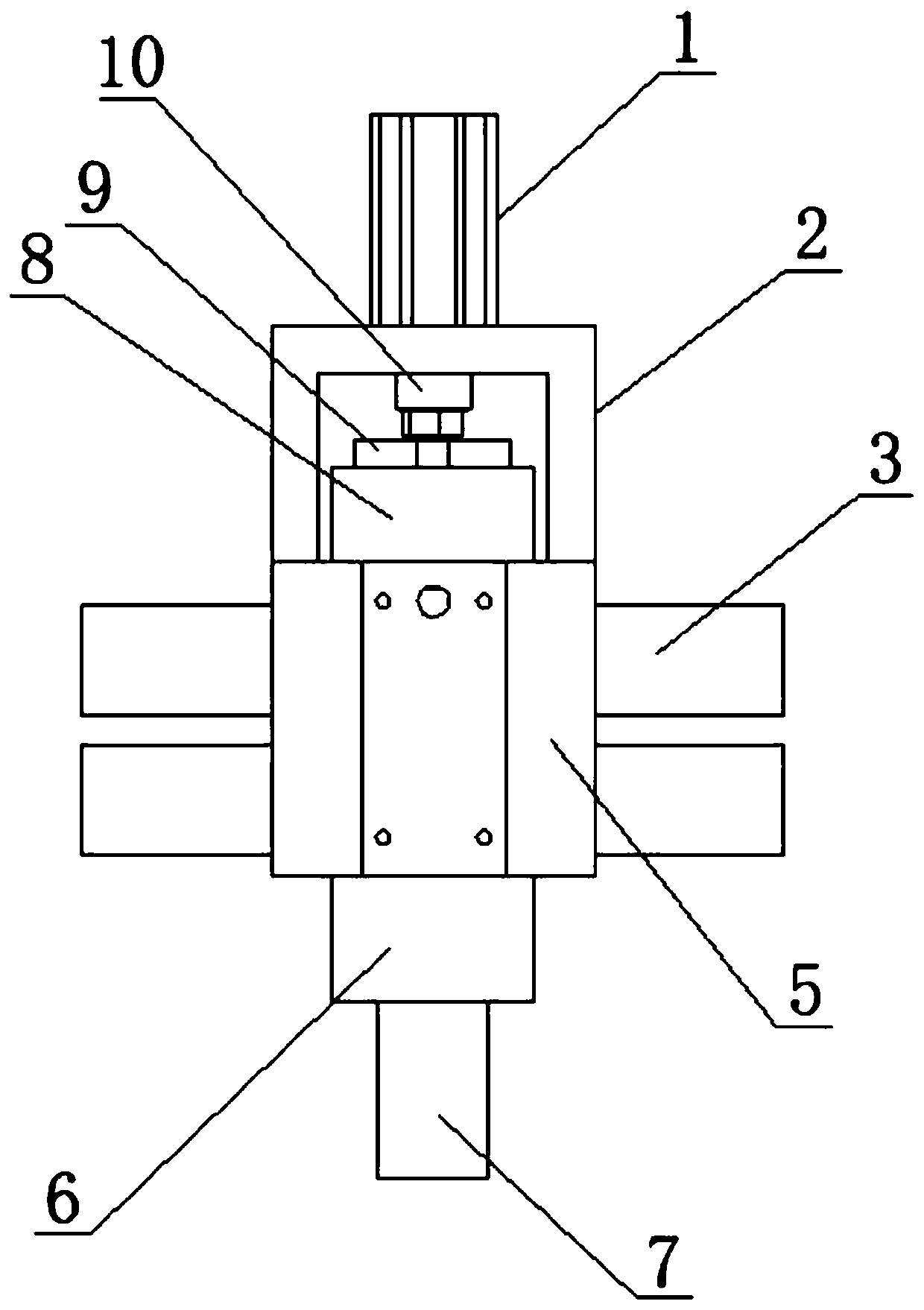
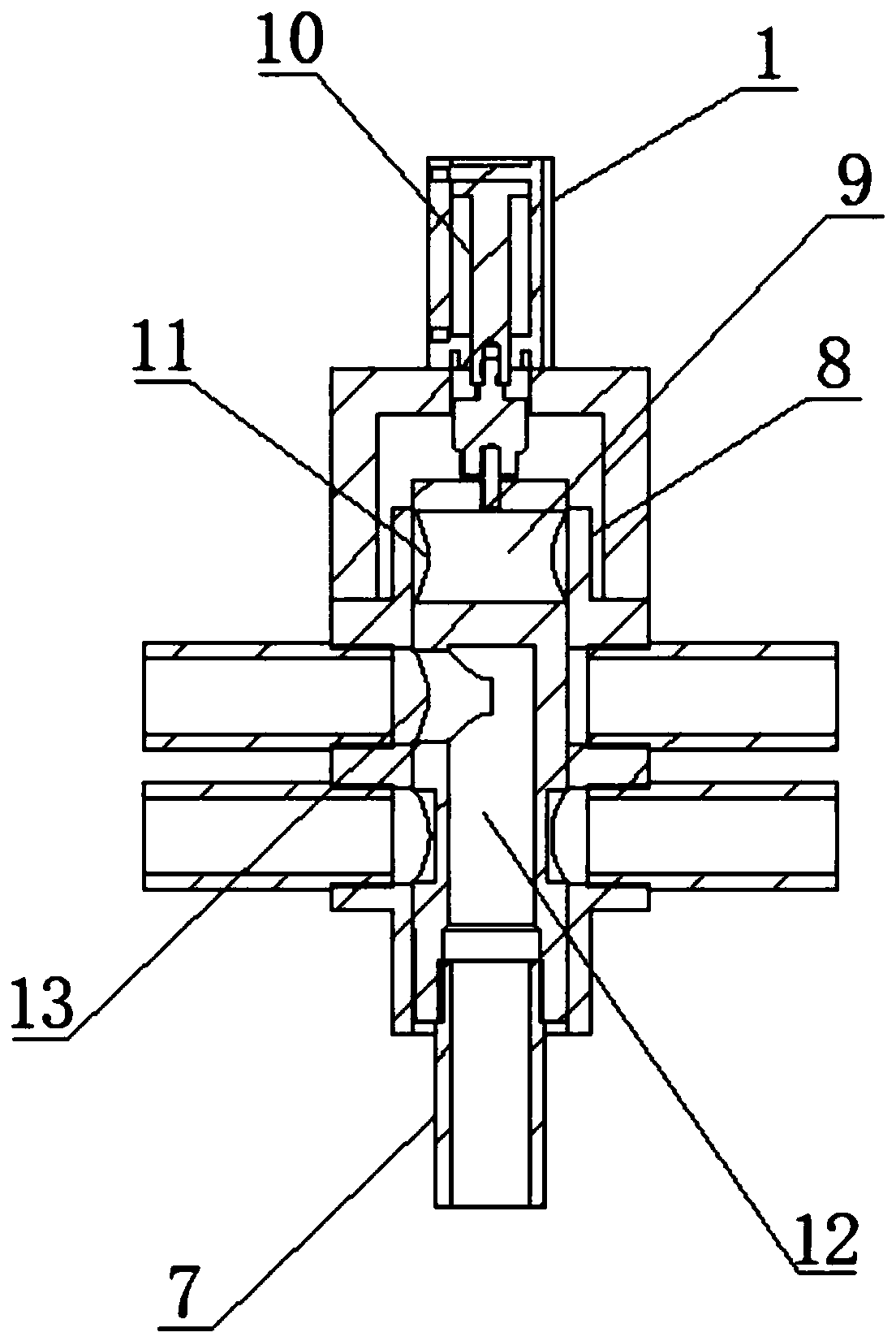
[0023] see Figure 1-5 , the present invention provides a technical solution: a strong switching valve, including a movable cylinder 1 and a fixed seat 2, the upper end of the fixed seat 2 is equipped with a movable cylinder 1, and the outer wall of the lower end of the fixed seat 2 is provided with a housing 5, the housing 5 is provided with fixing holes 4 on the outer wall of the front end, and there are four fixing holes 4 in total. The valve is fixedly co...


PUM


Abstract

The invention discloses a strong switching valve. The valve comprises a movable cylinder and a fixed seat, a movable cylinder is mounted at the upper end of the fixed seat; a shell is arranged on theouter wall of the lower end of the fixed seat; a fixing hole is formed in the outer wall of the front end of the shell; a connecting pipe is arranged on the outer wall of the right end of the shell; afixing ring is arranged on the outer wall of the lower end of the shell; a feeding hole extending downwards is formed in the circumferential outer wall of the lower end of the fixing ring; a powerfulswitching valve is designed; one end of the switching valve is connected with an air inlet and an air outlet of the air blower through two connecting pipes; strong suction force is provided for the switching valve through the air blower; the movable air cylinder at the upper end of the switching valve is used for controlling the movable rod in the switching valve to ascend and descend, suction and release of products can be completed through the action of the movable air cylinder, the problem that hollow products cannot be sucked due to insufficient suction force of a common switching valve is solved, and the production and conveying efficiency of the products is greatly improved.

Description

technical field [0001] The invention belongs to the related technical field of switching valves, and in particular relates to a powerful switching valve. Background technique [0002] The switching valve (forced valve) is a pneumatic switching valve installed at the hot end of the switching heat exchanger (or cold storage device). It uses the principle of connecting rod structure to realize the opening and closing of the valve plate. For air control, according to the different roles played in the process, there are air and contaminated nitrogen switching valves, pure nitrogen suppression valves, contaminated nitrogen three-way valves, etc. From the structure type, there are two types: vertical and horizontal, vertical switching The valve can be divided into two types: air-opening and air-closing. The air-opening means that when the signal compressed air is cut off, the disc can automatically open by its own weight, otherwise it is air-closing. The choice of air-opening and a...

Claims


Application Information

Patent Timeline
Patent Type & Authority Applications(China)
IPC IPC(8): F16K11/07F16K27/04F16K31/06F16K31/12
CPCF16K11/0716F16K27/041F16K31/061F16K31/12
Inventor 徐聪
Owner 苏州希瑞格机器人科技有限公司
Why Eureka
Try Eureka