
Debugging method and device for power acquisition terminal and power acquisition terminal

A technology of power collection and debugging method, which is applied in the direction of measuring devices, measuring electrical variables, instruments, etc., can solve the problems of low efficiency of on-site maintenance of power collection terminals, inconvenience of on-site debugging, etc., achieve convenient debugging operations, avoid malicious debugging, and improve efficiency effect

Active Publication Date: 2021-09-21
NINGBO SANXING MEDICAL & ELECTRIC CO LTD
View PDF13 Cites 0 Cited by
  • Summary
  • Abstract
  • Description
  • Claims
  • Application Information

AI Technical Summary

Problems solved by technology

Since the power collection terminal is usually installed in a place with a harsh environment, the method of connecting the serial port line to the PC brings inconvenience to on-site debugging, making the efficiency of on-site maintenance of the power collection terminal too low

Method used


Image

  • Debugging method and device for power acquisition terminal and power acquisition terminal
  • Debugging method and device for power acquisition terminal and power acquisition terminal
  • Debugging method and device for power acquisition terminal and power acquisition terminal

Examples


Embodiment Construction

[0029] In order to make the purpose, technical solutions and advantages of the embodiments of the present invention clearer, the technical solutions in the embodiments of the present invention will be clearly and completely described below in conjunction with the drawings in the embodiments of the present invention. Obviously, the described embodiments It is a part of embodiments of the present invention, but not all embodiments. The components of the embodiments of the invention generally described and illustrated in the figures herein may be arranged and designed in a variety of different configurations.

[0030] Accordingly, the following detailed description of the embodiments of the invention provided in the accompanying drawings is not intended to limit the scope of the claimed invention, but merely represents selected embodiments of the invention. Based on the embodiments of the present invention, all other embodiments obtained by persons of ordinary skill in the art wi...


PUM


Abstract

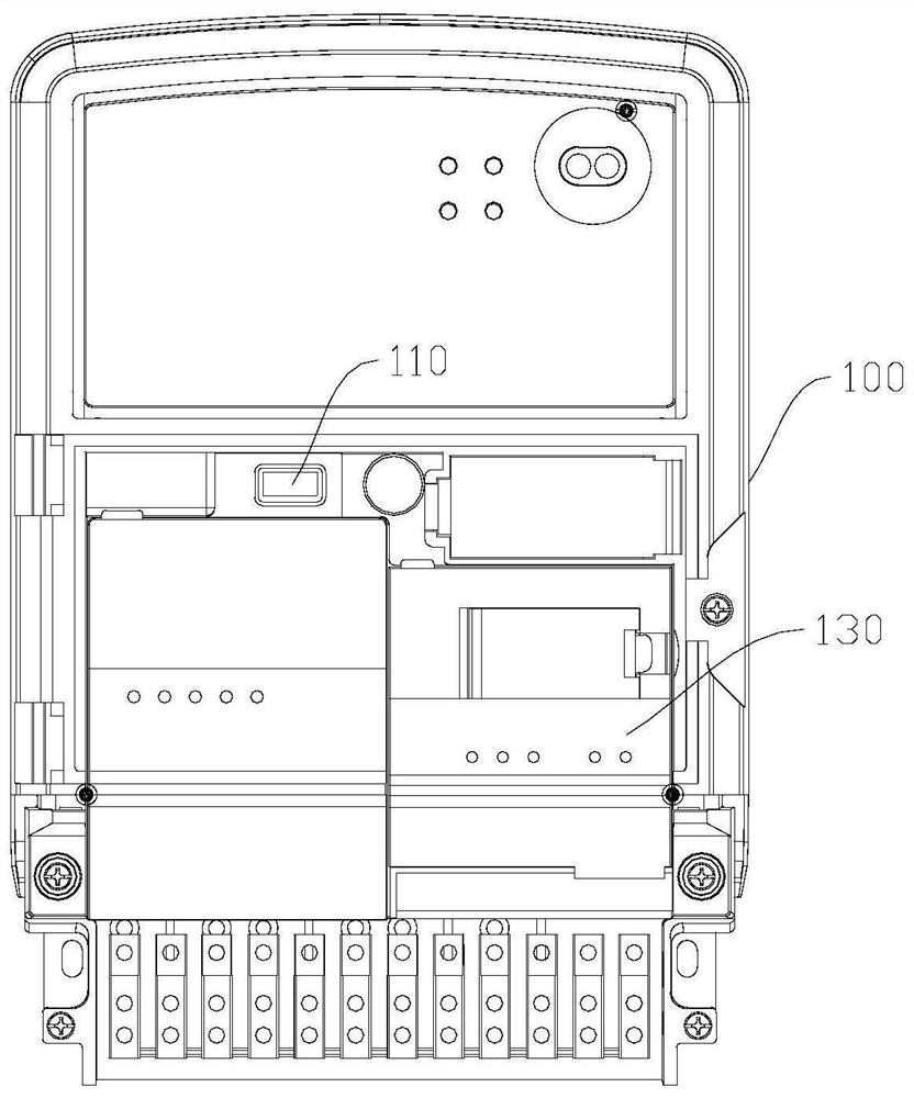
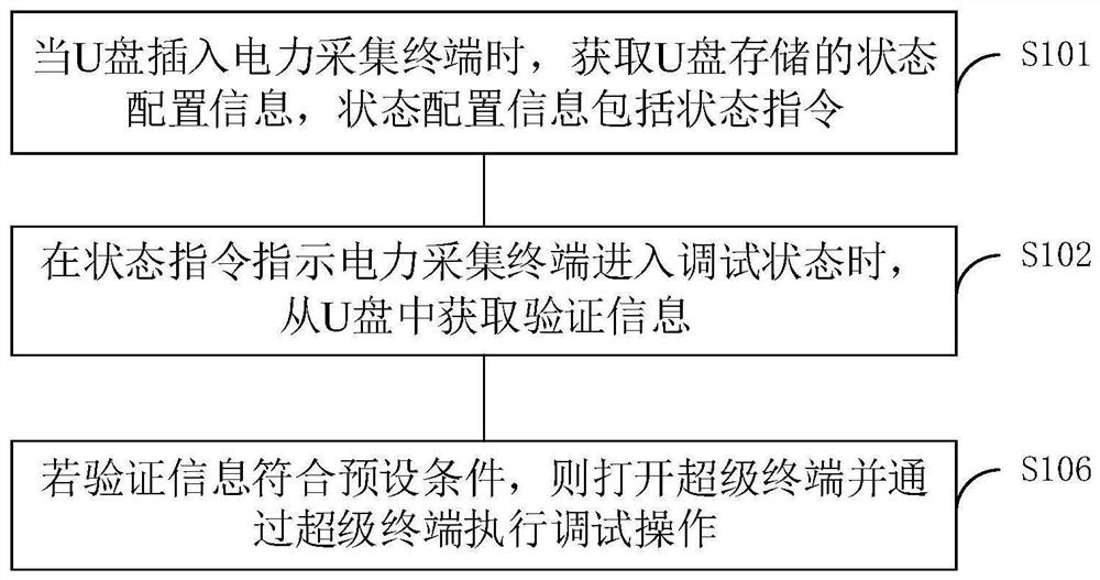
Embodiments of the present invention provide a debugging method and device for a power collection terminal and a power collection terminal, and relate to the technical field of smart meters. The debugging method includes: when the U disk is inserted into the power collection terminal, obtaining state configuration information stored in the U disk, the state configuration information including a state instruction; when the state instruction instructs the power collection terminal to enter a debugging state, obtaining verification information from the U disk; If the verification information meets the preset condition, the hyperterminal is opened and a debugging operation is performed through the hyperterminal. The embodiments of the present invention provide a debugging method and device for a power collection terminal and a power collection terminal, which can improve the efficiency of on-site debugging of the power collection terminal.

Description

technical field [0001] The invention relates to the technical field of smart meters, in particular to a debugging method and device for a power collection terminal and a power collection terminal. Background technique [0002] In recent years, with the steady development of my country's economy, the development of my country's smart meter industry is relatively mature, and the current number of power collection terminals in operation has reached more than 1 million. Due to the existence of on-site meter replacement, crosstalk in the station area, load switching, etc., the workload of on-site commissioning and setting of the power collection terminal has increased sharply. At present, the on-site debugging of the power collection terminal generally adopts a serial port line to connect with a PC (personal computer, personal computer) for corresponding communication and debugging operations. Because the power collection terminal is usually installed in a place with a harsh env...

Claims


Application Information

Patent Timeline
Patent Type & Authority Patents(China)
IPC IPC(8): G01R35/04
CPCG01R35/04
Inventor 陈文敏张强刘宁冯丹荣
Owner NINGBO SANXING MEDICAL & ELECTRIC CO LTD
Learn More