Chair rail fixing structure
A technology for fixing structures and clapboards, applied in building construction, covering/lining, construction, etc., can solve problems affecting the fixing effect and unsightly appearance, and achieve good fixing effect, good appearance and increased sense of space
- Summary
- Abstract
- Description
- Claims
- Application Information
AI Technical Summary
Problems solved by technology
Method used
Image
Examples
Embodiment 1
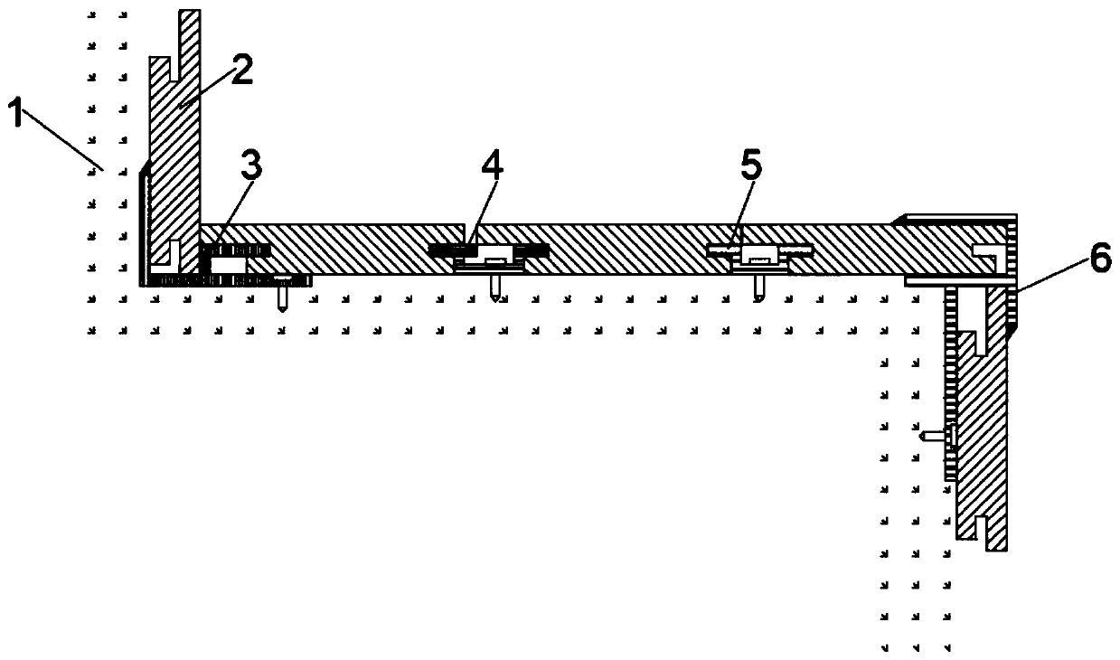
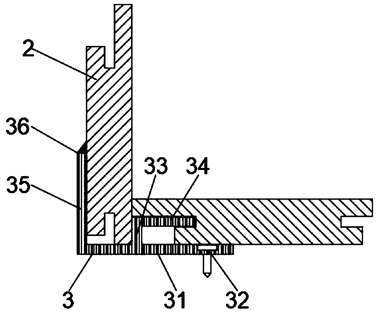
[0023] Embodiment one, by figure 1 , figure 2 with Figure 5 Given, including the wall body 1, the wall panel 2 is installed on the outside of the wall body 1, and the wall panel 2 at the inner right angle on the outer side of the wall body 1 is installed through the inner right angle fixing assembly 3, and the inner right angle fixing assembly 3 includes a first fixing plate 31 , screw hole 32, short clamping plate 33, first clamping plate 34, long clamping plate 35 and female corner 36, the top side of the first fixing plate 31 is provided with a screw hole 32, and the middle part of the top of the first fixing plate 31 is away from the screw One side of the hole 32 is vertically fixed with a short clamping plate 33, the top of the short clamping plate 33 is vertically fixed with a first clamping plate 34 near the end of the screw hole 32, and the top of the first fixing plate 31 is vertically fixed at the end position away from the screw hole 32. The long clamping plate ...
Embodiment 2
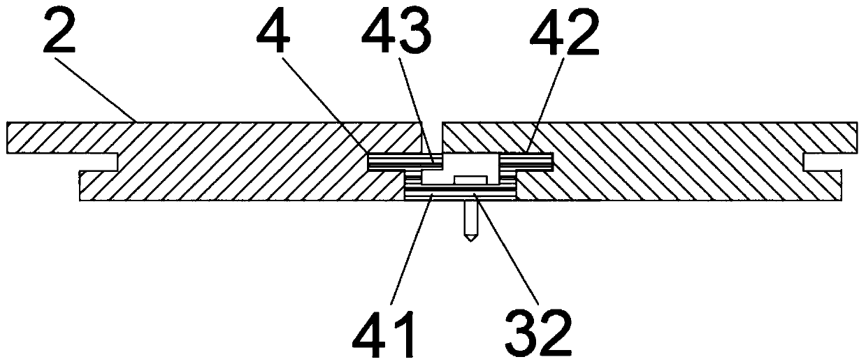
[0024] Embodiment two, on the basis of embodiment one, by image 3 Given, the first horizontal fixing assembly 4 includes a U-shaped plate 41, a second clamping plate 42, a space plate 43 and screw holes 32, a screw hole 32 is provided on one side of the middle part of the U-shaped plate 41, and both sides of the top of the U-shaped plate 41 are A second clamping plate 42 is vertically fixed outward, and a space plate 43 is vertically fixed outwardly at the same horizontal position as the second clamping plate 42 on the top side of the U-shaped plate 41, so as to facilitate the installation at the horizontal position of the body of wall 1 .
Embodiment 3
[0025] Embodiment three, on the basis of embodiment one, by Figure 4 Given, the second horizontal fixing assembly 5 includes a U-shaped plate 41, a second clamping plate 42 and a screw hole 32, a screw hole 32 is provided on one side of the middle part of the U-shaped plate 41, and both sides of the top of the U-shaped plate 41 are vertically fixed outwards. There is a second clamping plate 42, which increases the installation method at the horizontal position of the body of wall 1, so that it can be selected and used.
PUM
 Abstract
Description
Claims
Application Information
 - R&D Engineer
- R&D Manager
- IP Professional
- Industry Leading Data Capabilities
- Powerful AI technology
- Patent DNA Extraction
Browse by: Latest US Patents, China's latest patents, Technical Efficacy Thesaurus, Application Domain, Technology Topic, Popular Technical Reports.
© 2024 PatSnap. All rights reserved.Legal|Privacy policy|Modern Slavery Act Transparency Statement|Sitemap|About US| Contact US: help@patsnap.com


