
Anti-theft lock with modular drive device

A driving device and modular technology, applied in the field of anti-theft locks, can solve the problems of poor lock body stability, long time consumption, easy loss of gear parts, etc., to achieve the effect of enhancing stability and reliability, shortening replacement time, and improving maintenance efficiency

Pending Publication Date: 2019-12-06
广东好太太智能家居有限公司
View PDF5 Cites 2 Cited by
  • Summary
  • Abstract
  • Description
  • Claims
  • Application Information

AI Technical Summary

Problems solved by technology

[0003] And the most easily damaged part in the existing anti-theft lock body is the drive device therein. Because several gears in the lock body are generally fixed on the shell plate of the lock body by rotating shafts, and each gear is meshed with each other. Cooperate with each other to rotate, if a gear in the lock body is abnormal, it will lead to the linkage of the entire driving device, affecting the normal operation of each structure in the lock body
[0004] If you want to replace one of the gears, first, you need to disassemble the shell plate of the lock body, but at this time, the gears connected to the shell plate are prone to drop; afterwards, due to the tight fit between the gears, if To replace a certain gear, it is necessary to remove all the gears linked with the gear from the shell plate of the lock body. After the gears are replaced, the several gears are spliced ​​back into the lock body. The whole replacement process is complicated and time consuming. It takes a long time to improve the maintenance efficiency, and the scattered gear parts are easy to lose when they are removed. After replacing the new gears, there may be adjacent gears that cannot mesh perfectly, resulting in poor stability of the lock body.

Method used


Image

  • Anti-theft lock with modular drive device
  • Anti-theft lock with modular drive device
  • Anti-theft lock with modular drive device

Examples


Embodiment Construction

[0030] Below, the present invention will be further described in conjunction with the accompanying drawings and specific implementation methods. It should be noted that, under the premise of not conflicting, the various embodiments described below or the technical features can be combined arbitrarily to form new embodiments. .

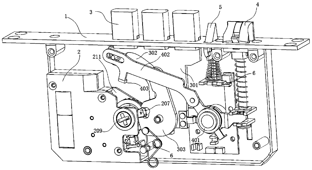
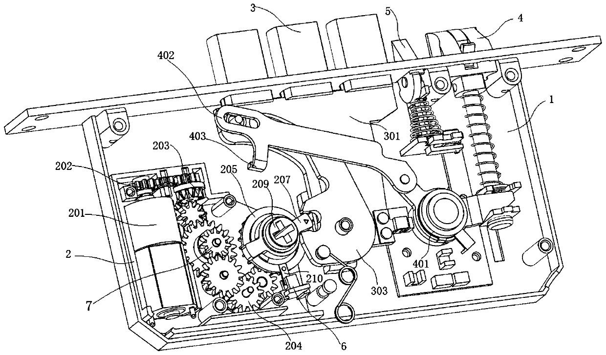
[0031] An anti-theft lock with a modular drive, such as figure 1 As shown, the modular driving device is detachably installed in the lock body 1, and the entire module can be replaced when it needs to be replaced, which can improve the replacement efficiency, and can be modularized to improve production efficiency.

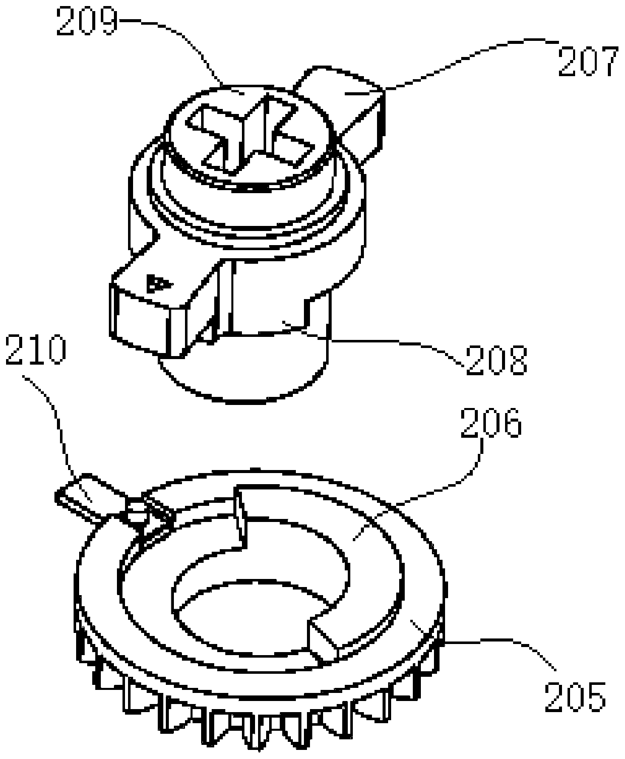
[0032] In this embodiment, the anti-theft lock is set as an electronic lock, and the lock body 1 has a deadbolt and a transmission device. like Figure 1~5 As shown, in this embodiment, the transmission device includes a main deadbolt transmission mechanism and an oblique bolt transmission mechanism, wherein the main deadbolt transmissio...


PUM


Abstract

The invention discloses an anti-theft lock with a modular drive device. The anti-theft lock comprises a lock body and a driving module. A spring bolt and a transmission device are arranged in the lockbody. The transmission device is connected with the spring bolt. The driving module comprises a driving box body and a driving mechanism. The driving box body is arranged in the lock body. A notch isformed in the side, close to the transmission device, of the driving box body. The driving mechanism is fixed in the driving box body. One end of the driving mechanism is exposed in the notch and islinked with the transmission device, so that the driving device drives the transmission device to eject the spring bolt out of the lock body or withdraw the spring bolt into the lock body. According to the anti-theft lock with the modular drive device, a plurality of gears in the driving device are arranged in the box body connected with the lock body, when the gears in the driving device need tobe replaced, only the whole box body needs to be detached from the lock body, the replacement action can be completed by replacing the box body with a new box body internally provided with driving gears, the situation that gears are scattered and fall off is avoided, the maintenance efficiency of the lock body is improved, and the stability and reliability of the lock body can be improved.

Description

technical field [0001] The invention relates to the field of door locks, in particular to an anti-theft lock with a modular driving device. Background technique [0002] At present, anti-theft locks are widely used in various occasions due to their high security. Existing anti-theft locks are provided with driving devices, such as several gears installed in the lock body, through which the gears rotate in cooperation with each other to push the closing of the mechanical switch in the lock body to complete the unlocking and locking actions. [0003] And the most easily damaged part in the existing anti-theft lock body is the drive device therein. Because several gears in the lock body are generally fixed on the shell plate of the lock body by rotating shafts, and each gear is meshed with each other. Cooperate with each other and rotate, if a gear in the lock body is abnormal, it will cause the linkage of the entire driving device, affecting the normal operation of each struc...

Claims


Application Information

Patent Timeline
IPC IPC(8): E05B47/00E05B63/14E05B15/00
CPCE05B47/0012E05B47/026E05B63/146E05B15/00E05B2047/002
Inventor 沈汉标王妙玉童威云黄安川黄克洲夏亮
Owner 广东好太太智能家居有限公司
Learn More