
Carton sheet pushing device used in packaging field

A technology for pushing devices and cartons, which is applied in the directions of packaging, transportation and packaging, thin material handling, etc. It can solve the problems that affect the reliability and efficiency of pushing devices and the large resistance of carton pieces, so as to achieve small pushing resistance, reliable pushing and high efficiency. high effect

Active Publication Date: 2019-12-10
SUNKISS HEALTHCARE ZHEJIANG
View PDF4 Cites 1 Cited by
  • Summary
  • Abstract
  • Description
  • Claims
  • Application Information

AI Technical Summary

Problems solved by technology

[0003] At present, the packaging sheet materials used in the packaging field are mostly metal half sheets, carton sheets, plastic or composite single-sheet materials; during the packaging process, the packaging materials are first cut into individual sheets and plates according to the specified size and shape, or Make carton sheets with creases, metal covers, etc. When packaging, they are neatly stacked in the storage warehouse, and the sheets are sent to the packaging station one by one through the push mechanism to complete the subsequent packaging process. The push of the shaped material usually adopts various push devices such as mechanical friction lead, push, vacuum sucker, glue, combination of mechanical and vacuum, etc. The side is pushed out, so that every time the carton piece is pushed out, it will be subjected to the gravity exerted by all the carton pieces on the upper side, so that the resistance on the lowermost carton piece becomes larger, which affects the pushing reliability of the pushing device sex and efficiency

Method used


Image

  • Carton sheet pushing device used in packaging field
  • Carton sheet pushing device used in packaging field
  • Carton sheet pushing device used in packaging field

Examples


Embodiment Construction

[0046] The specific implementation manners of the present invention will be further described in detail below in conjunction with the accompanying drawings and embodiments. The following examples or drawings are used to illustrate the present invention, but not to limit the scope of the present invention.

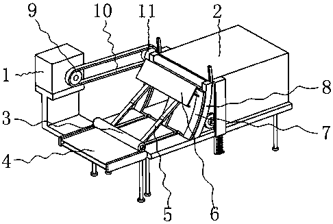
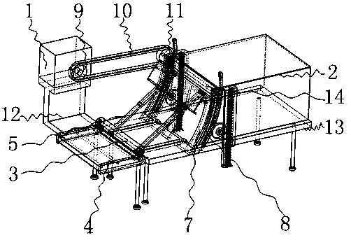
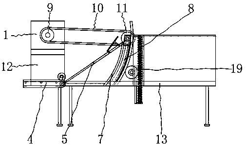
[0047] Such as figure 1 , 2 As shown, it includes a geared motor 1, a paper storage case 2, a guiding telescopic plate 5, a conveying mechanism 4, a bottom plate 13, a paper stopper 7, a paper licking roller, an arc guide rail 8, an arc slider 29, and a first fixed shaft 28 , where as Figure 18 As shown, the four corners of the lower side of the base plate 13 are respectively fixedly equipped with a second support rod 23 supporting the base plate 13, and the upper side of one end of the base plate 13 is symmetrically provided with two square grooves 42, and the effect of the square grooves 42 is to The downward swing of the corresponding guide expansion plate 5 provides...


PUM


Abstract

The invention belongs to the technical field of carton sheet pushing, and particularly relates to a carton sheet pushing device used in packaging field. The carton sheet pushing device comprises a speed reducing motor, a sheet storage shell, a guide telescopic plate, a conveying mechanism, a bottom plate, a sheet blocking plate and a sheet licking roller. In the case of a traditional carton sheetpushing device, carton sheets of the device are pushed out from the lower side of the sheet storage shell, and the carton sheets which are to be pushed each time is subjected to the gravity exerted from the other carton sheets located on the upper side, so that the carton sheets located on the lower side suffer big resistance. Compared with the traditional carton sheet pushing device, a pushing opening of the carton sheet pushing device used in the packaging field is located on the upper side of the sheet storage shell, so that the pushed carton sheets are not affected by other carton sheets after being pushed each time, and pushing resistance is small; and in addition, according to the designed pushing device, the pressure of the sheet licking roller exerted on the carton sheets is stable, and meanwhile a small pressure is kept, so that the normal movement of the carton sheets cannot be influenced due to overlarge pressure of the sheet licking roller on the carton sheets.

Description

[0001] Technical field [0002] The invention belongs to the technical field of carton piece pushing, and in particular relates to a carton piece pushing device used in the packaging field. Background technique [0003] At present, the packaging sheet materials used in the packaging field are mostly metal half sheets, carton sheets, plastic or composite single-sheet materials; during the packaging process, the packaging materials are first cut into individual sheets and plates according to the specified size and shape, or Make carton sheets with creases, metal covers, etc. When packaging, they are neatly stacked in the storage warehouse, and the sheets are sent to the packaging station one by one through the push mechanism to complete the subsequent packaging process. The push of the shaped material usually adopts various push devices such as mechanical friction lead, push, vacuum sucker, glue, combination of mechanical and vacuum, etc. The side is pushed out, so that every t...

Claims


Application Information

Patent Timeline
Patent Type & Authority Applications(China)
IPC IPC(8): B65H3/06
CPCB65B43/14
Inventor 马艳王益之赖江耀
Owner SUNKISS HEALTHCARE ZHEJIANG
Learn More