Fault type judgment system and method based on transient wave recording type fault indicators

A fault indicator and fault type technology, which is applied in the detection of faults by conductor type, fault location, information technology support system, etc., can solve the problems of difficulty in judging fault types, inaccurate judgment, and difficult to meet the user's high efficiency and high precision, etc. Achieving the effect of reducing troubleshooting time

Pending Publication Date: 2019-12-10
SHANDONG ZHIYANG ELECTRIC
View PDF3 Cites 5 Cited by
  • Summary
  • Abstract
  • Description
  • Claims
  • Application Information

AI Technical Summary

Benefits of technology

This patented technique uses an algorithm that records how well things are going wrong when there's any problem with them during their use period. If something goes through this way it sends its own messages back up to the main device where they were processed by another module called the base station controller (BSC). These modules then calculate what happened if anything was happening right before sending these signals over again. They send all those same results back down into the BSC which helps keep track everything about who has caused trouble later.

Problems solved by technology

This patented technical problem addressed by this patents relates to identifying potential causes of electrical arcs between two conductors that may lead to failure or other issues during use of an AC circuit (AC). Current methods require manual inspections from service technicians who can only determine if any one particular wire should break down before replacing them with another new cable. These techniques have limitations due to their subjectivity and lack accuracy, making it challenging to identify possible root causes without damaging expensive components like switchgear devices used at substations.

Method used


Image

  • Fault type judgment system and method based on transient wave recording type fault indicators
  • Fault type judgment system and method based on transient wave recording type fault indicators
  • Fault type judgment system and method based on transient wave recording type fault indicators

Examples


Embodiment 1

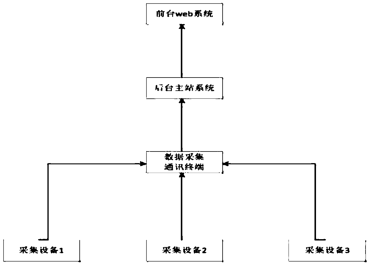
[0032] Refer to the accompanying drawings in the manual figure 1 , Figure 10 , Figure 11 , the described system and method for judging a fault type based on a transient wave recording type fault indicator, comprising a transient state recording wave type fault indicator installed on a power line, a data acquisition communication terminal, a foreground web system and a background master station system; the fault indicator performs wave recording and fault diagnosis on the current state of the line in real time, and sends its own attribute information and related action information to the data acquisition communication terminal through radio frequency communication, and the data acquisition communication terminal then transmits the fault information through 4G communication After receiving multiple sets of fault action information of the transient wave recording fault indicator through Ethernet, the background master system obtains relevant data and performs intelligent judgm...

Embodiment 2

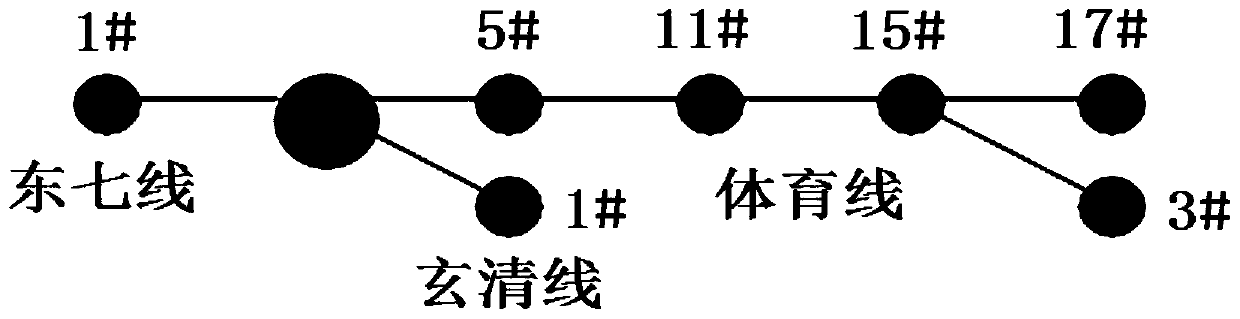
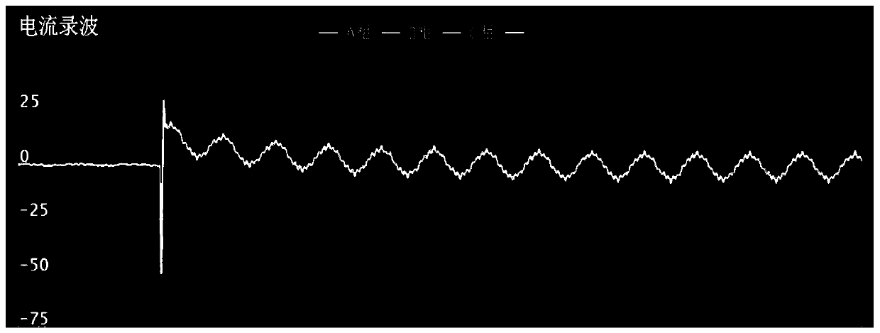
[0053] Such as figure 2 As shown, in the metal grounding test of No. 1 pole of 15# branch of Shanting Line, the current recording wave is as follows image 3 and Figure 4 as shown,

[0054] The poles 5# and 11# of the Shanting line are located on the fault path of the faulty line. When metallic grounding occurs, the electric field of the line will decrease instantaneously, and the current of the grounding item will increase instantaneously. In this way, when the zero-sequence current is synthesized, the zero-sequence The current will increase instantaneously, and at the same time, the zero-sequence current at the fault point will have the same mutation direction, and at the same time, it will suddenly change downwards. The transient peak value is large and the waveform height is similar. The ground fault type here is metallic grounding.

[0055] Such as Figure 5 and Figure 6 As shown, the 15 3# poles and 17# poles of the Shanting Line are located downstream of the faul...


PUM


Abstract

The invention relates to the field of fault type judgment, and particularly relates to a fault type judgment system and method based on transient recording type fault indicators. The fault indicatorsperform wave recording and fault diagnosis on the current state of a line in real time; the attribute information and related action information are sent to a data acquisition communication terminal through wireless radio frequency communication; the data acquisition communication terminal transmits the fault information to a background master station system through 4G communication; and after thebackground master station system receives the fault action information of the multiple groups of transient wave recording fault indicators through the Ethernet, a fault type is finally generated anddisplayed in a web system, and the fault type is pushed to a mobile phone of a maintenance engineer or convenient maintenance equipment to assist the maintenance engineer in determining fault positioning. According to the judgment system and method, a user can quickly locate a fault occurrence point and judge the type to solve the problem, and a new intelligent distribution line monitoring systemcapable of replacing manual monitoring is formed.

Description


Claims


Application Information

Patent Timeline
Owner SHANDONG ZHIYANG ELECTRIC
Why Eureka
Try Eureka