Intelligent monitoring system for power system SF6 switching station

An intelligent monitoring and power system technology, which is applied in the direction of liquid tightness measurement using liquid/vacuum degree, measuring device, and detecting the appearance of fluid at the leakage point, etc., can solve the problem that timeliness and safety cannot be fully guaranteed, Data misreading, sudden changes in system gas content cannot be reflected in time, etc.

Inactive Publication Date: 2010-11-24
上海哈德电气技术有限公司
View PDF7 Cites 20 Cited by
  • Summary
  • Abstract
  • Description
  • Claims
  • Application Information

AI Technical Summary

Problems solved by technology

[0002] In the field of gas state monitoring of power equipment, the traditional detection method is that the monitoring personnel visit the site to visually monitor the SF6 gas density relay installed on the site. The reading habit of the system and the installation of the density relay on the system site are not good for gas monitoring, and the sudden change of the gas content in the system cannot be reflected in time, which poses a severe challenge to the reliability of the system
[0003] At the same time, the traditional method of leak location is to equip protective clothing and enter the site for detection after the monitoring personnel are informed of the density relay alarm. According to the actual situation, the bubbling method and air density method are used to detect the location of the leak point. The point efficiency is low, the workload of the operators is heavy, the timeliness and safety cannot be fully guaranteed, and it conflicts with the intelligent grid equipment in today's society, and the problem cannot be solved quickly and effectively, and the contradiction is prominent

Method used


Image

  • Intelligent monitoring system for power system SF6 switching station
  • Intelligent monitoring system for power system SF6 switching station
  • Intelligent monitoring system for power system SF6 switching station

Examples


Embodiment Construction

[0019] Embodiments of the present invention will now be described in detail with reference to the accompanying drawings.

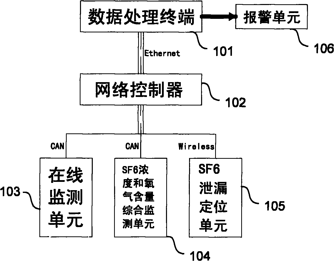
[0020] figure 1 A schematic structural block diagram of the intelligent monitoring system of the present invention is shown. Such as figure 1 As shown, the intelligent monitoring system of the present invention includes a data processing terminal 101, a network controller 102, an online monitoring unit 103, a comprehensive monitoring unit 104 for SF6 concentration and oxygen content, a SF6 leakage location unit 105 and an alarm unit 106. In this embodiment, the online monitoring unit 103 and the SF6 concentration and oxygen content comprehensive monitoring unit 104 are connected with the network controller 102 via the CAN bus to realize the bidirectional transmission of data, while the SF6 leakage location unit 105 is wirelessly connected with the network controller 102 connections for automatic tracking of equipment and seamless connection of data. In ...


PUM


Abstract

The invention provides an intelligent monitoring system for a power system SF6 switching station. The system comprises a network controller, a data processing terminal, an alarm unit, an on-line monitoring unit, an SF6 concentration and oxygen content comprehensive monitoring unit and an SF6 leakage positioning unit, wherein the data processing terminal is connected to the network controller; the alarm unit is connected with the data processing terminal and used for sending alarm according to the indication of the data processing terminal; the on-line monitoring unit, the SF6 concentration and oxygen content comprehensive monitoring unit and the SF6 leakage positioning unit are in signal connection with the data processing terminal through the network controller respectively; the SF6 leakage positioning unit is mobile; the on-line monitoring unit monitors the power system SF6 switching station in real time and transmits a detection signal to the data processing terminal through the network controller; and when abnormity is detected, the data processing terminal starts the SF6 concentration and oxygen content comprehensive monitoring unit to reduce a fault point range and then starts the SF6 leakage positioning unit to automatically track a fault point position. The intelligent monitoring system can analyze and process system abnormity in time to realize intelligent monitoring.

Description

technical field [0001] The invention relates to the field of electric equipment detection, in particular to an integrated device for monitoring the gas state and leak location in the SF6 switching station of the electric power system. Background technique [0002] In the field of gas state monitoring of power equipment, the traditional detection method is that the monitoring personnel visit the site to visually monitor the SF6 gas density relay installed on the site. The reading habit of the system and the installation of the density relay on the system site are not good for gas monitoring, and the sudden change of the gas content in the system cannot be reflected in time, which poses a severe challenge to the reliability of the system. [0003] At the same time, the traditional method of leak location is to equip protective clothing and enter the site for detection after the monitoring personnel are informed of the density relay alarm. According to the actual situation, the...

Claims


Application Information

Patent Timeline
Patent Type & Authority Applications(China)
IPC IPC(8): G01N33/00G01M3/04G08B25/00
Inventor 周学生
Owner 上海哈德电气技术有限公司
Why Eureka
Try Eureka