Switch cabinet
A switchgear and support plate technology, applied in the field of switchgear, can solve the problems of wasted area inside the switchgear, inconvenient replacement of electrical components, inability to adjust and install, etc., so as to improve the efficiency of the maintenance system, save the relative distance, and improve the clamping adhesion. Effect
- Summary
- Abstract
- Description
- Claims
- Application Information
AI Technical Summary
Problems solved by technology
Method used
Image

Examples
specific Embodiment approach
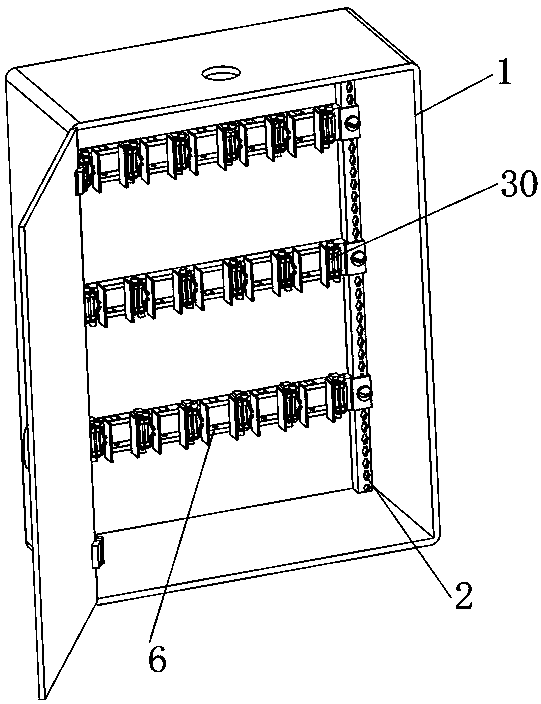
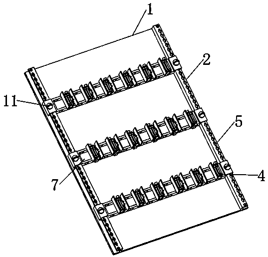
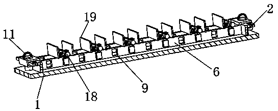
[0029] Specific implementation method: When the distance between the various compartments inside the switch cabinet needs to be adjusted, the two rotating plates 11 at both ends of the connecting shell 6 are rotated respectively, so that the two rotating plates 11 drive the two clamping rods 10 to support The inside of the clamping hole 5 of the plate 2 is rotated, and when the clamping rod 10 is rotating, the two limiting blocks 13 are aligned with the limiting holes 16 on the positioning plate 9, and are aligned with the opening on the buffer shell 14. Correspondingly, the rotating plate 11 is then pulled upwards, so that the two stoppers 13 are separated from the snapping holes 5 on the opening support shell of the buffer shell 14 under the action of the connection of the snapping rod 10, and then the alignment of the positioning plate 9 is realized. The role of detachment from the support plate 2, at this time, it can be adjusted according to the model of the electrical com...
PUM
 Abstract
Description
Claims
Application Information
 - R&D Engineer
- R&D Manager
- IP Professional
- Industry Leading Data Capabilities
- Powerful AI technology
- Patent DNA Extraction
Browse by: Latest US Patents, China's latest patents, Technical Efficacy Thesaurus, Application Domain, Technology Topic.
© 2024 PatSnap. All rights reserved.Legal|Privacy policy|Modern Slavery Act Transparency Statement|Sitemap