Vehicle-mounted wireless charging device and vehicle-mounted armrest box using vehicle-mounted wireless charging device

A vehicle-mounted wireless and charging device technology, applied in the direction of circuit devices, battery circuit devices, collectors, etc., can solve the problems of easy restriction of effective charging area layout, unsuitable charging, poor design flexibility of effective charging area, etc., and achieve wireless charging efficiency Ease, the effect of improving compatibility

Pending Publication Date: 2019-12-10
NIO ANHUI HLDG CO LTD
View PDF0 Cites 0 Cited by
  • Summary
  • Abstract
  • Description
  • Claims
  • Application Information

AI Technical Summary

Problems solved by technology

[0005] The current mainstream on-board wireless charging solutions basically conform to the Qi standard. Therefore, the corresponding on-board wireless charging device uses three Litz (Litz) coils in a row for charging, so that the effective charging area provided by it is enlarged to suit Charging of smartphones; however, the layout of the effective charging area of ​​the Litz coil is easily restricted, the design flexibility of the effective charging area is poor, and it is not suitable for electronic products with relatively small charging power (such as various wearable smart terminals) Charge

Method used


Image

  • Vehicle-mounted wireless charging device and vehicle-mounted armrest box using vehicle-mounted wireless charging device
  • Vehicle-mounted wireless charging device and vehicle-mounted armrest box using vehicle-mounted wireless charging device
  • Vehicle-mounted wireless charging device and vehicle-mounted armrest box using vehicle-mounted wireless charging device

Examples


Embodiment Construction

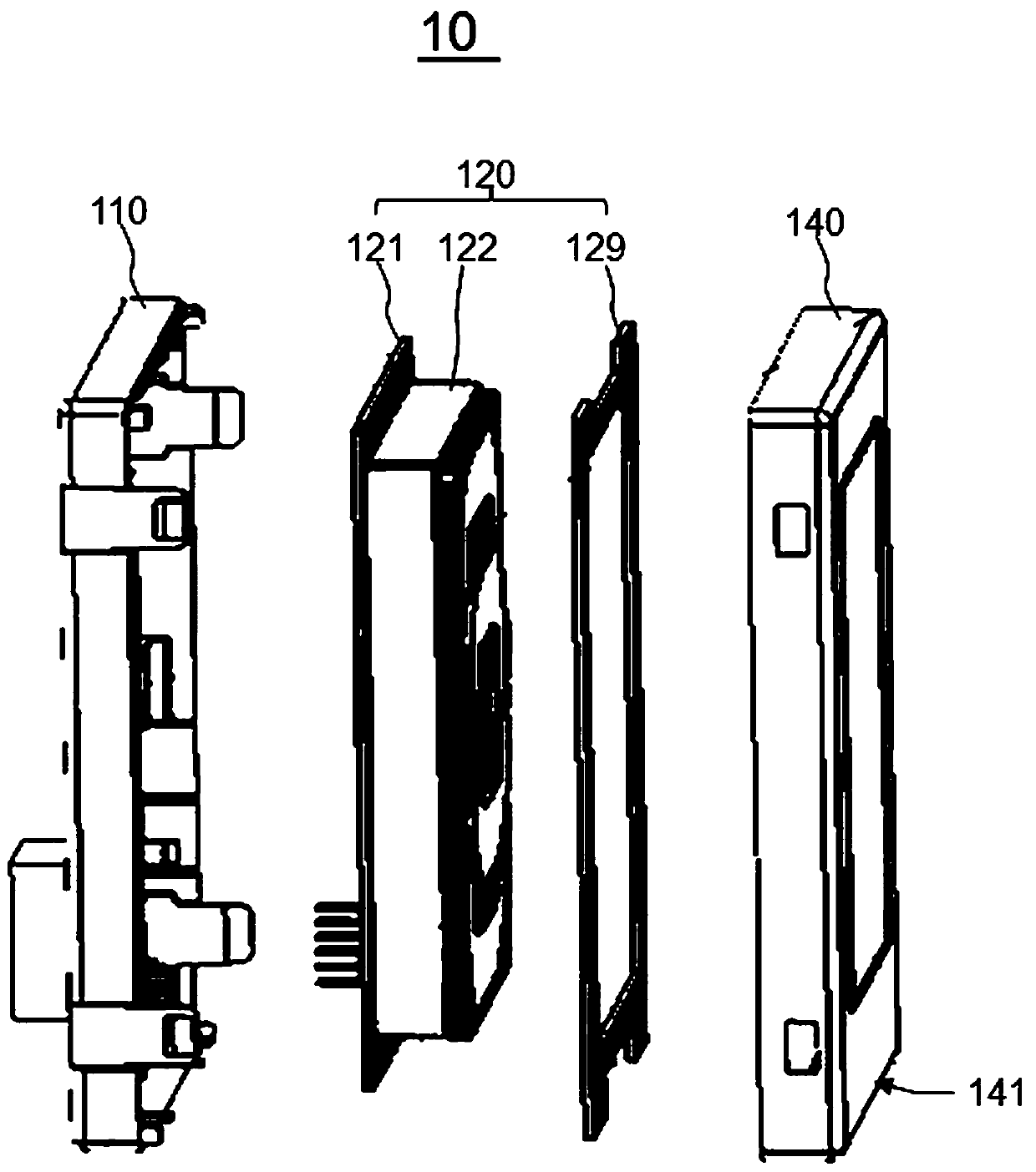
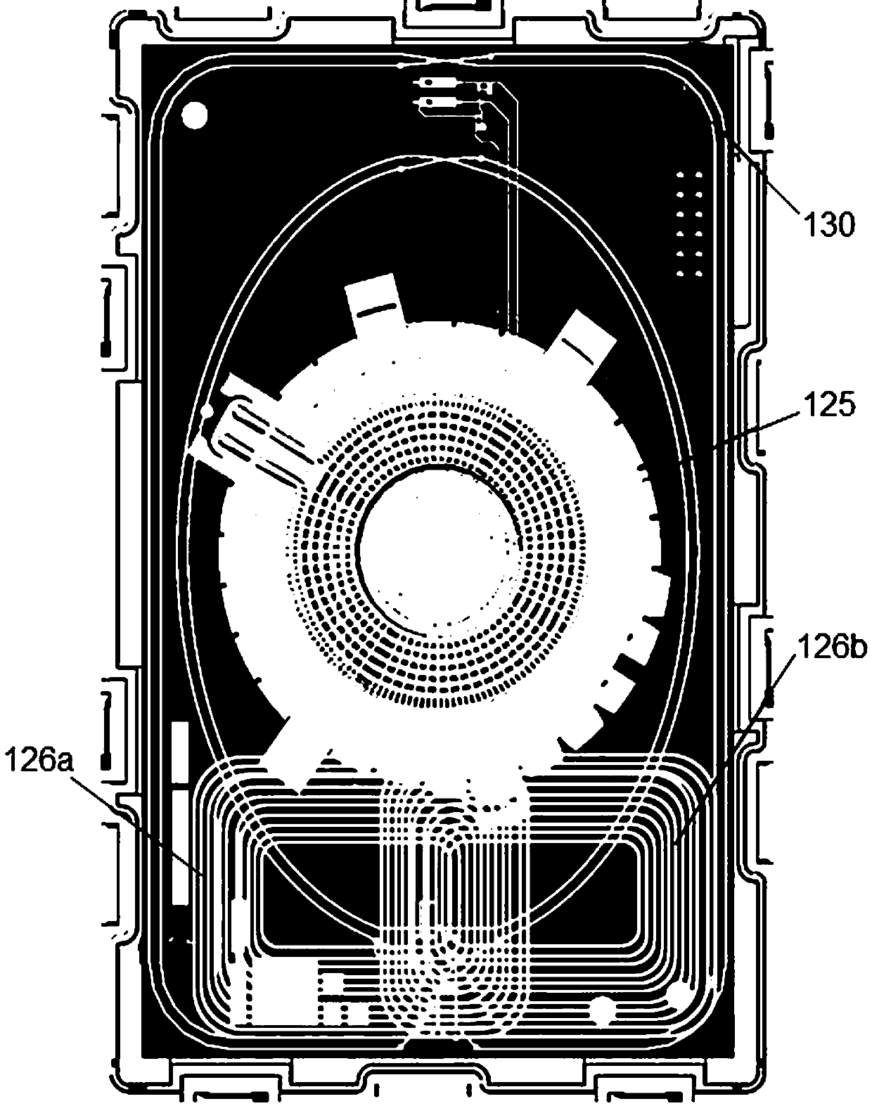
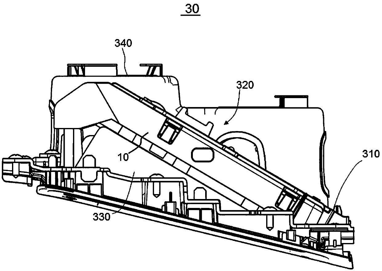
[0035] For purposes of brevity and illustration, the principles of the invention are described herein primarily with reference to exemplary embodiments thereof. However, those skilled in the art will readily recognize that the same principles are equally applicable to and may be implemented in all types of on-vehicle wireless charging devices and / or wireless charging methods using in-vehicle wireless charging devices, Any such changes do not depart from the true spirit and scope of this patent application.

[0036] Moreover, in the following description, reference is made to the accompanying drawings, which illustrate certain exemplary embodiments. Electrical, mechanical, logical and structural changes may be made to these embodiments without departing from the spirit and scope of the present invention. Furthermore, although a feature of the invention is disclosed in connection with only one of several implementations / embodiments, such feature may be combined with other imple...


PUM


Abstract

The invention relates to a vehicle-mounted wireless charging device and a vehicle-mounted armrest box using the vehicle-mounted wireless charging device, and belongs to the technical field of wirelesscharging. The vehicle-mounted wireless charging device is used for wirelessly charging an electronic product and comprises a plurality of primary coils used for providing inductive energy to the electronic product. The vehicle-mounted wireless charging device is characterized in that a plurality of primary coils include a first coil and a second coil which is formed on a printed circuit board. The second coil provides lower charging power relative to the first coil, and the second coil is arranged at a different position relative to the first coil so that the first coil and the second coil are respectively suitable for providing the inductive energy to the electronic product with different charging power requirements and sizes. The wireless charging area of the vehicle-mounted wireless charging device has good design flexibility and can simultaneously meet the wireless charging requirements of various types of electronic products with different powers and sizes so as to have good vehicle-mounted wireless charging experience.

Description

technical field [0001] The invention belongs to the technical field of wireless charging, and relates to a vehicle-mounted wireless charging device. Background technique [0002] With the wide application of mobile phones, smart watches, etc. as consumer electronic products, there are more and more charging demands for consumer electronic products. For example, consumers have charging demands for various consumer electronic products when riding in vehicles. [0003] At present, consumers are no longer satisfied with charging various electronic products or electronic products such as mobile phones by relying on the wired charging method of connecting the wiring harness, and hope to use wireless charging (WirelessPower Transfer, WPT) which is more convenient and has a better experience. Therefore, for example, vehicles are generally equipped with on-board wireless charging devices to charge electronic products such as mobile phones. [0004] However, electronic products are d...

Claims


Application Information

Patent Timeline
Patent Type & Authority Applications(China)
IPC IPC(8): H02J50/10H02J7/00B60R16/033
CPCB60R16/033H02J50/10
Inventor 吴凤占于尔根张蕊史晓磊
Owner NIO ANHUI HLDG CO LTD
Why Eureka
Try Eureka