Antenna switching method, device and equipment and computer readable storage medium

An antenna switching and antenna technology, applied in the field of communication, can solve problems such as unresolved, increased electromagnetic wave absorption ratio, etc.

Inactive Publication Date: 2019-12-10
ZTE CORP
View PDF3 Cites 2 Cited by
  • Summary
  • Abstract
  • Description
  • Claims
  • Application Information

AI Technical Summary

Problems solved by technology

The above method has the following problems: After the antenna is switched, it will work on the antenna with better performance, but at the same time it may cause the problem of an increase in the SAR (Specific Absorption Rate, electromagnetic wave absorption ratio or absorption ratio). The heat energy generated by electromagnetic waves is a measure of the impact on the human body, and the unit is W / Kg (watts / kg)
How to make a trade-off between the two indicators of signal quality and SAR value, the current general methods have not solved it

Method used


Image

  • Antenna switching method, device and equipment and computer readable storage medium
  • Antenna switching method, device and equipment and computer readable storage medium
  • Antenna switching method, device and equipment and computer readable storage medium

Examples


Embodiment 1

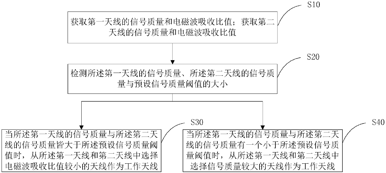
[0050] Such as figure 1 As shown, in this embodiment, an antenna switching method includes:

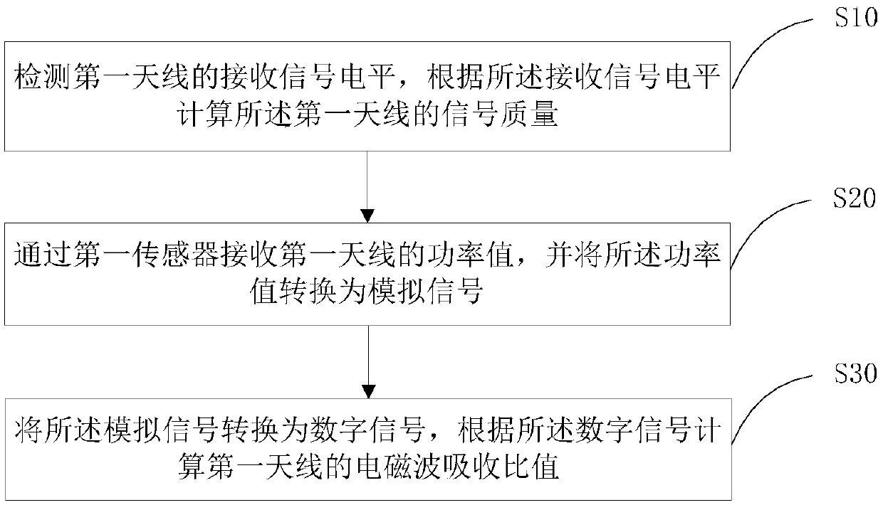
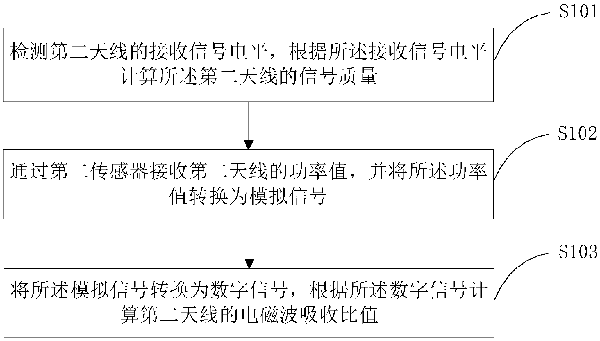
[0051] S10. Obtain the signal quality and electromagnetic wave absorption ratio of the first antenna; acquire the signal quality and electromagnetic wave absorption ratio of the second antenna;

[0052] S20. Detect the signal quality of the first antenna, the signal quality of the second antenna, and a preset signal quality threshold;

[0053] S30. When both the signal quality of the first antenna and the signal quality of the second antenna are greater than the preset signal quality threshold, select an antenna with a smaller electromagnetic wave absorption ratio from the first antenna and the second antenna as a working antenna;

[0054] S40. When either the signal quality of the first antenna or the signal quality of the second antenna is less than the preset signal quality threshold, select an antenna with a higher signal quality from the first antenna and the second antenna as...

Embodiment 2

[0073] Such as Figure 6 As shown, in this embodiment, an antenna switching device includes:

[0074] An acquisition module 10, configured to acquire the signal quality and electromagnetic wave absorption ratio of the first antenna, and acquire the signal quality and electromagnetic wave absorption ratio of the second antenna;

[0075] A detection module 20, configured to detect the signal quality of the first antenna, the signal quality of the second antenna, and a preset signal quality threshold;

[0076] A switching module 30, configured to select an electromagnetic wave absorption ratio from the first antenna and the second antenna when both the signal quality of the first antenna and the signal quality of the second antenna are greater than the preset signal quality threshold The smaller antenna is used as a working antenna; it is also used to transmit signals from the first antenna and the second antenna when one of the signal quality of the first antenna and the signal...

Embodiment 3

[0092] In this embodiment, an electronic device includes a memory, a processor, and at least one application program stored in the memory and configured to be executed by the processor, and the application program is configured to execute The antenna switching method described in the first embodiment.


PUM


Abstract

The invention discloses an antenna switching method, device and equipment, and a computer readable storage medium, and belongs to the technical field of communication. The method comprises the steps of obtaining signal quality and an electromagnetic wave absorption ratio of two antennas; detecting the signal quality of the first antenna, the signal quality of the second antenna and a preset signalquality threshold; when the signal quality of the first antenna and the signal quality of the second antenna are both greater than a preset signal quality threshold, selecting the antenna with a smaller electromagnetic wave absorption ratio as a working antenna; when one of the signal quality of the first antenna and the signal quality of the second antenna is smaller than a preset signal qualitythreshold, selecting the antenna with higher signal quality as a working antenna; by detecting and comparing the current signal receiving quality of the two or more antennas with the SAR value, carrying out switching, so that the terminal works on the antenna with better signal quality and smaller SAR value, the harm to a human body is avoided, the received signal of the terminal is improved, anda user has better user experience.

Description

technical field [0001] This article relates to the field of communication technologies, and in particular to an antenna switching method, device, equipment, and computer-readable storage medium. Background technique [0002] With the development of the communication industry, the standards that mobile terminals need to support cover 2G, 3G, and 4G. In the 4G era, terminal antennas need to support more frequency bands and wider bandwidths. Business requirements such as CA and MIMO also put forward higher requirements for antennas. At the same time, the appearance of the terminal is becoming more and more important. Metal machines that meet the higher aesthetic requirements of users have also become popular, but at the same time, the antenna indicators will deteriorate and the work performance will decrease; on the other hand, people are becoming more and more concerned about their health. We always hope that electronic products will have the least impact on our health and saf...

Claims


Application Information

Patent Timeline
Patent Type & Authority Applications(China)
IPC IPC(8): H04B7/08H04B7/06
CPCH04B7/0602H04B7/0608H04B7/0805H04B7/04H04B7/06H04B7/08
Inventor 范景云
Owner ZTE CORP
Why Eureka
Try Eureka