Antenna and electronic equipment including antenna

An electronic equipment and antenna technology, applied in the field of antennas and electronic equipment, can solve the problems of small antenna clearance area, large height requirements, and small antenna sub-integration

Inactive Publication Date: 2015-11-25
HOLYPAO
View PDF3 Cites 0 Cited by
  • Summary
  • Abstract
  • Description
  • Claims
  • Application Information

AI Technical Summary

Problems solved by technology

[0003] Traditional mobile phone antennas are all single-tuned, with large headroom requirements and high requirements for height. There is no large headroom and a certain height, and the bandwidth is generally very narrow, which cannot meet the broadband requirements. Then there are products with metal casings. More and more, the sub-integration of multiple antennas is getting smaller and smaller, and the headroom of each antenna is getting smaller and smaller, so there is an urgent need for an antenna with a small headroom requirement and a wider frequency band to meet the above requirements

Method used


Image

  • Antenna and electronic equipment including antenna
  • Antenna and electronic equipment including antenna

Examples


Embodiment 1

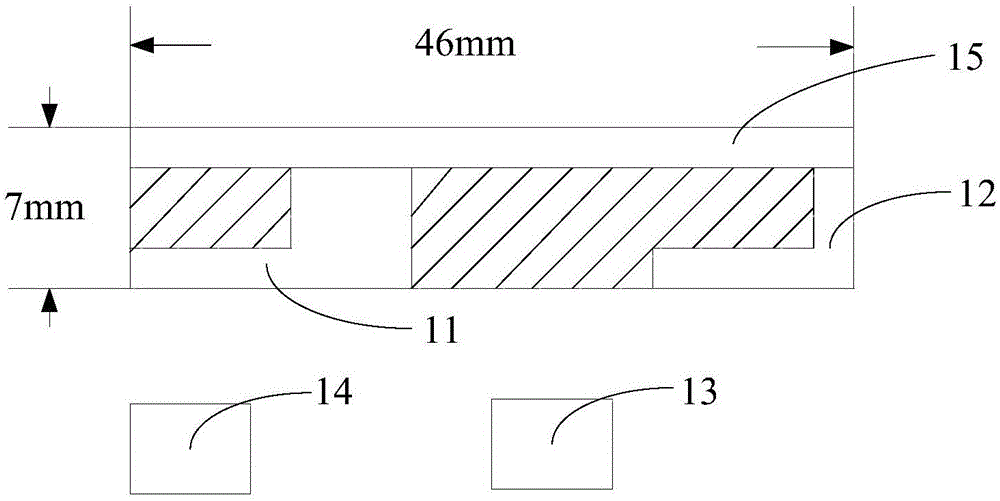
[0033] Embodiment 1 is an antenna 1 provided by the embodiment of the present invention, refer to figure 1 As shown, the antenna 1 includes:

[0034] A high frequency module 11, a low frequency module 12, a switch module 13, a matching module 14 and a power feeding module 15;

[0035] One end of the high frequency module 11 is connected to the feed module 15, and one end of the low frequency module 12 is connected to the feed module 15;

[0036] The high frequency module 11 and the low frequency module 12 are L-shaped components respectively;

[0037] The high frequency module 11 and the low frequency module 12 are located in the clearance area;

[0038] By arranging the low-frequency module and the high-frequency module in an L-shape, the low-frequency module and the high-frequency module can be located in the clearance area as much as possible, thereby ensuring the efficiency of receiving and sending signals by the antenna.

[0039] The high-frequency module 11 is used fo...

Embodiment 2

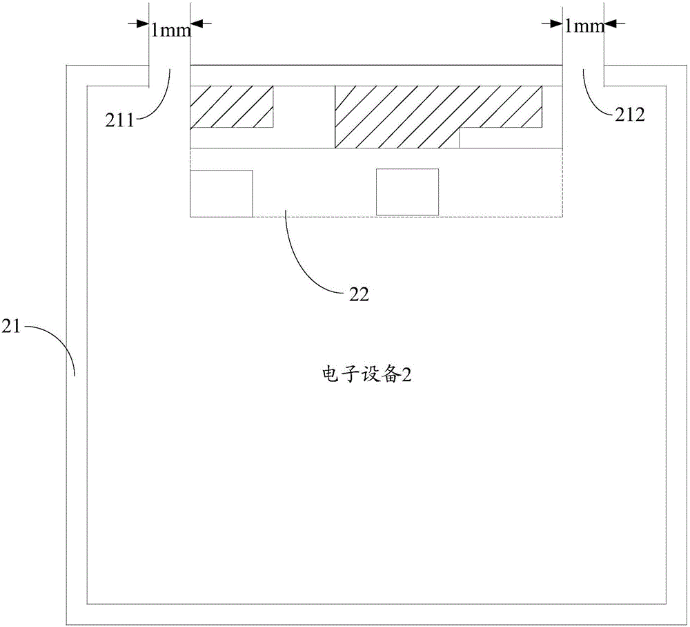
[0055] Embodiment 2 is an electronic device 2 including the antenna provided by the embodiment of the present invention, refer to figure 2 As shown, the electronic device 2 includes:

[0056] A metal frame 21 and the antenna 22 described in the first embodiment.

[0057] The metal frame 21 includes at least a first breaking point 211 and a second breaking point 212,

[0058] The first breakpoint and the second breakpoint are located on the short side of the metal frame, and the antenna is connected to the feed module included in the antenna.

[0059] In practical applications, the widths of the first breakpoint and the second breakpoint are respectively 1 mm;

[0060] By arranging the first breakpoint and the second breakpoint on the metal frame, the shielding of the signal is avoided, and the reception of the signal by the antenna is realized.

[0061] optional,

[0062] The high-frequency module of the antenna is arranged on the structure where the clearance area in the...


PUM


Abstract

The invention discloses an antenna and electronic equipment including the antenna, belonging to the field of communication. Embodiments of the invention provide the antenna and the electronic equipment including the antenna. The antenna comprises a high-frequency module, a low-frequency module, a switch module, a matching module and a feed module, wherein one end of the high-frequency module is connected to the feed module, and one end of the low-frequency module is connected to the feed module; the high-frequency module and the low-frequency module are L-shaped components respectively, wherein the high-frequency module and the low-frequency module are located in a clearance area; the high-frequency module is used for receiving a high-frequency signal and the low-frequency module is used for receiving a low-frequency signal; the matching module is used for transmitting any one of the high-frequency signal and the low-frequency signal; and the switch module is used for controlling the antenna for receiving any one of the high-frequency signal and the low-frequency signal. The antenna is not only smaller in size, but switchover of the antenna between reception of the high-frequency signal and reception of the low-frequency signal is implemented, and the frequency application range of the antenna is further improved.

Description

technical field [0001] The present invention relates to the communication field, in particular to an antenna and electronic equipment including the antenna. Background technique [0002] With the development of the times and people's demand for mobile phone performance, mobile phones are developing in the direction of large screen, ultra-thin, multi-functional full metal frame. The antenna is also developed towards the trend of small size and wide application range of frequency, so as to meet the development direction of mobile phones. [0003] Traditional mobile phone antennas are all single-tuned, with large headroom requirements and high requirements for height. There is no large headroom, and a certain height. The bandwidth is generally very narrow, which cannot meet the broadband requirements, and there are metal casing products. More and more, the sub-integration of multiple antennas is getting smaller and smaller, and the headroom of each antenna is getting smaller a...

Claims


Application Information

Patent Timeline
Patent Type & Authority Applications(China)
IPC IPC(8): H01Q1/24H01Q5/30
Inventor 胡志清
Owner HOLYPAO
Why Eureka
Try Eureka