Processing method for correcting low steepness optical mirror surface error

A technology of optical mirror surface and processing method, which is applied in the field of correction of optical mirror surface error, and can solve problems such as increasing processing cost, increasing dwell time, and inaccurate acquisition of removal function

Inactive Publication Date: 2009-06-17
NAT UNIV OF DEFENSE TECH
View PDF0 Cites 29 Cited by
  • Summary
  • Abstract
  • Description
  • Claims
  • Application Information

AI Technical Summary

Problems solved by technology

In the former implementation, the motion system always starts and stops frequently, which affects the stable operation of the ion source and increases the dwell time
The accurate speed method uses the speed change ladder diagram to calculate the system realization speed. It needs to know the dynamic parameters of the system in advance. The speed calculation process is complicated. For the linkage system whose dynamic parameters are diffic

Method used


Image

  • Processing method for correcting low steepness optical mirror surface error
  • Processing method for correcting low steepness optical mirror surface error
  • Processing method for correcting low steepness optical mirror surface error

Examples


Embodiment 1

[0071] This embodiment is carried out on the ion beam polishing equipment (KDIFS-500 type can be selected), and the ion beam modification process parameters are set as follows: the working gas is argon, and the working vacuum is 0.8×10 -2 Pa, ion energy 1100eV, beam current 25mA. The polished component to be processed is a CVD SiC glass-ceramic plane with a diameter of 90 mm.

[0072] Carry out ion beam polishing to above-mentioned glass-ceramic plane by following method step:

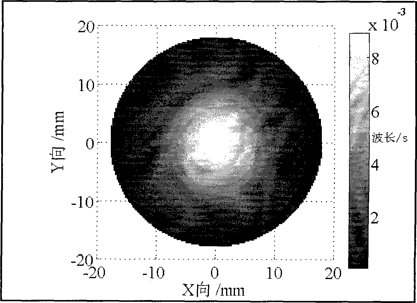
[0073] 1. Determine the removal function: apply the above-mentioned ion beam modification process to carry out the removal function test, and the obtained removal function is denoted as R(x, y), and its distribution is as follows figure 1 As shown, the radius R of the removal function t =18mm; the removal function is discretized into a 37×37 square matrix at an interval of S=1mm, and the square matrix of the removal function obtained by the discretization is denoted as R, and the efficiency paramete...

Embodiment 2

[0086] This embodiment is carried out on the ion beam polishing equipment (KDIFS-500 type can be selected), and the ion beam modification process parameters are set as follows: the working gas is argon, and the working vacuum is 0.8×10 -2Pa, ion energy 1100eV, beam current 25mA. The polished component to be processed is an ordinary glass-ceramic spherical surface with a diameter of 196 mm.

[0087] The ion beam polishing is carried out to the described glass-ceramics by the following method steps:

[0088] 1. Determine the removal function: apply the above-mentioned ion beam modification process to carry out the removal function test, and the obtained removal function is denoted as R(x, y), and its distribution is as follows figure 1 As shown, the radius R of the removal function t =18mm; the removal function is discretized into a 37×37 square matrix with an interval of S=1mm, and the square matrix of the removal function obtained by the discretization is denoted as R, and ...


PUM

PropertyMeasurementUnit
Radiusaaaaaaaaaa

Abstract

The invention discloses a processing method for correcting error of a low-gradient optical mirror surface, which comprises the following steps: firstly acquiring a removal function through experiment, then using a wave surface interferometer to acquire a surface shape error function of an element, dispersing the surface shape error function, programming a processing path at the same time, extending the surface shape error function, establishing a model and solving processing residence time, carrying out numerical control processing by using the solved residence time, identifying error and controlling accuracy for the processed result, so as to finish processing. The processing method has the advantages of high process efficiency, low processing cost and good error correction effect, and can effectively correct the surface shape error of the low-gradient optical mirror surface.

Description

technical field [0001] The invention relates to a correction technology for optical mirror surface errors, in particular to a processing method for correcting optical mirror surface errors by using the Bayesian principle. Background technique [0002] With the continuous improvement of performance requirements of modern optical systems, the quality requirements of optical components are also continuously improved. Modern optical components are developing in the direction of aspheric, lightweight and thin, large relative aperture, etc., and the error of each frequency band of the mirror needs to be strictly controlled. At the same time, due to the huge number of parts of modern optical systems and high precision requirements, traditional manual processing methods can no longer meet the requirements of precision and efficiency. The traditional manufacturing methods of optical parts have gradually changed from "small tool grinding head", It is replaced by advanced optical part...

Claims


Application Information

Patent Timeline
IPC IPC(8): C03C23/00
Inventor 李圣怡戴一帆焦长君解旭辉周林彭小强
Owner NAT UNIV OF DEFENSE TECH
Why Eureka
Try Eureka