Sand mixer with material cleaning mechanism

A sand mixer and material cleaning technology, which is applied in the cleaning/processing machinery of casting mold materials, casting molding equipment, metal processing equipment, etc., can solve the problems of sand mixer damage, waste of molding sand resources, and removal of molding sand, etc. Achieve the effect of improving quality, reducing waste and increasing sufficiency

Active Publication Date: 2019-12-13
辽宁晟华耐火材料有限公司
View PDF10 Cites 3 Cited by
  • Summary
  • Abstract
  • Description
  • Claims
  • Application Information

AI Technical Summary

Problems solved by technology

[0002] As a device for mixing molding sand, sand mixer is widely used in the foundry industry. During the sand mixing process of traditional sand mixers, molding sand often sticks to the inside of the sand mixer shell, resulting in sand mixing. If it is not uniform, it cannot ensure that the molding sand mixing reaches the required standard, which affects the quality of the molding sand and cannot meet the needs of foundry production. At the same time, the binder will also bond the molding sand to the inner wall of the sand mixer shell. When sanding, it may not be possible to remove the mixed molding sand completely, and it will stick to the shell of the sand mixer for a long time. After the molding sand hardens, it will become very troublesome to clear it from the shell of the sand mixer. When mixing sand, hard particles will be produced in the molding sand, which cannot meet the requirements of use, resulting in a waste of molding sand resources. At the same time, some operators prevent the molding sand from sticking to the sand mixer shell by beating the sand mixer shell. This is easy to cause damage to the sand mixer and affect the service life of the sand mixer, which needs to be improved urgently

Method used


Image

  • Sand mixer with material cleaning mechanism
  • Sand mixer with material cleaning mechanism
  • Sand mixer with material cleaning mechanism

Examples


Embodiment Construction

[0023] The following will clearly and completely describe the technical solutions in the embodiments of the present invention with reference to the accompanying drawings in the embodiments of the present invention. Obviously, the described embodiments are only some, not all, embodiments of the present invention. Based on the embodiments of the present invention, all other embodiments obtained by persons of ordinary skill in the art without making creative efforts belong to the protection scope of the present invention.

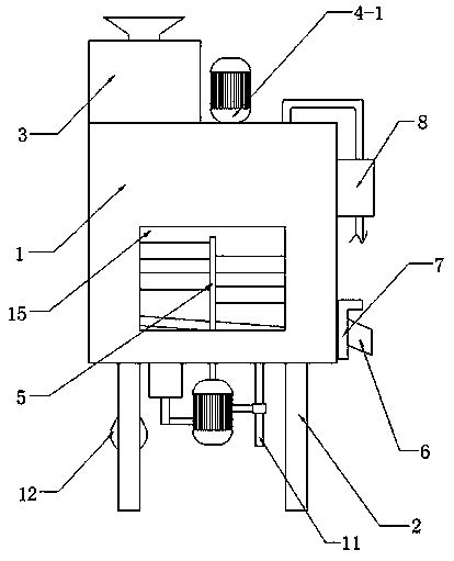
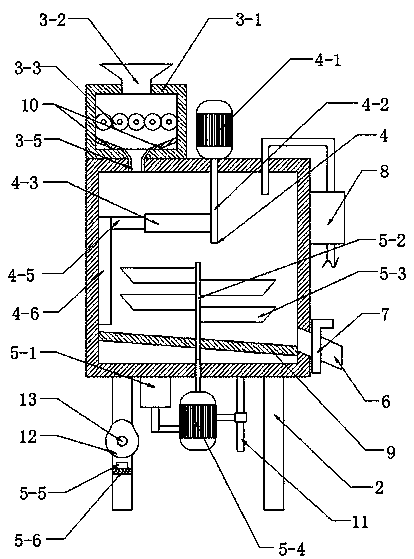
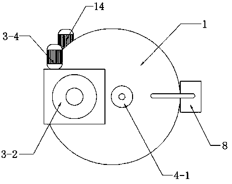
[0024] Such as Figure 1-Figure 4 As shown, this specific embodiment adopts the following technical scheme: it includes a box body 1, a leg 2, a crushing mechanism 3, a cleaning mechanism 4, a mixing mechanism 5, a discharge pipe 6, a one-way valve 7 and a water pump 8, and the box The four corners of the lower surface of the body 1 are welded and fixed with legs 2, and the front side wall of the box body 1 is embedded with an observation window 15, which is c...


PUM


Abstract

The invention discloses a sand mixer with a material cleaning mechanism, and relates to the technical field of sand mixers. A pressure grinding mechanism is arranged on the left side of the upper endof a box body, and an outer shell in the pressure grinding mechanism is fixed to the left side of the upper surface of the box body; the material cleaning mechanism is arranged on the upper side inside the box body, a second motor in the material cleaning mechanism is fixed to the upper side wall of the box body, a mixing mechanism is arranged on the lower side of the material cleaning mechanism,and a cylinder in the mixing mechanism is fixed to the left side of the lower surface of the box body; a discharge pipe is inserted into the lower end of the right side wall of the box body, the middle end of the discharge pipe is provided with a one-way valve, a water pump is arranged on the upper side of the one-way valve, the water pump is fixed to the upper end of the right side wall of the box bod, and a water outlet of the water pump is connected with the interior of the box body through a pipeline; and the material cleaning mechanism is arranged on the upper side of the interior of thesand mixer. The inner side wall of the box body is cleaned through the material cleaning mechanism, molding sand on the side wall is scraped into the box body, and the molding sand is prevented from being stuck on the inner side wall of the box body, so that resource waste is reduced; and the sand mixer has the advantages of being reasonable in arrangement, low in manufacturing cost and the like.

Description

technical field [0001] The invention relates to the technical field of sand mixers, in particular to a sand mixer with a cleaning mechanism. Background technique [0002] As a device for mixing molding sand, sand mixer is widely used in the foundry industry. During the sand mixing process of traditional sand mixers, molding sand often sticks to the inside of the sand mixer shell, resulting in sand mixing. If it is uneven, it cannot ensure that the molding sand mixing reaches the required standard, which affects the quality of the molding sand and cannot meet the needs of foundry production. At the same time, the binder will also bond the molding sand to the inner wall of the sand mixer shell. When sanding, it may not be possible to remove the mixed molding sand completely, and it will stick to the sand mixer shell for a long time. After the molding sand is hardened, it will become very troublesome to clear it from the sand mixer shell. When mixing sand, hard particles will ...

Claims


Application Information

Patent Timeline
Patent Type & Authority Applications(China)
IPC IPC(8): B22C5/04
CPCB22C5/044B22C5/0472
Inventor 杨文晶邓道君王计振肖宇程邓忠顺
Owner 辽宁晟华耐火材料有限公司
Why Eureka
Try Eureka