Electric ground anchor hammering installation device

A technology for installing devices and ground anchors, applied in the directions of striking tools, light impact tools, manufacturing tools, etc., can solve the problems of weak wind resistance of distribution network poles, threats to economic development, and low work efficiency, saving manpower , easy to use, improve work efficiency

Pending Publication Date: 2019-12-13
GUANGDONG POWER GRID CO LTD +1
View PDF0 Cites 4 Cited by
  • Summary
  • Abstract
  • Description
  • Claims
  • Application Information

AI Technical Summary

Problems solved by technology

However, typhoons frequently occur in coastal areas, and the poles of distribution network lines in coastal areas of Guangdong are not strong in wind resistance, threatening local economic development
Therefore, it is necessary to windproof and strengthen the poles of distribution network lines in coastal areas. However, in the on-site construction, the ground anchors of the poles are installed by manual hammering, which is time-consuming and laborious, and the work efficiency is low.

Method used


Image

  • Electric ground anchor hammering installation device
  • Electric ground anchor hammering installation device

Examples


Embodiment 1

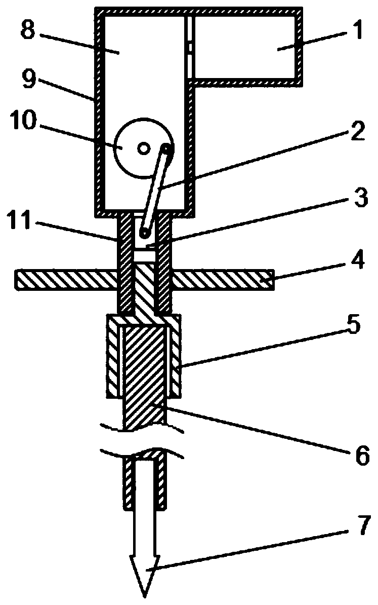
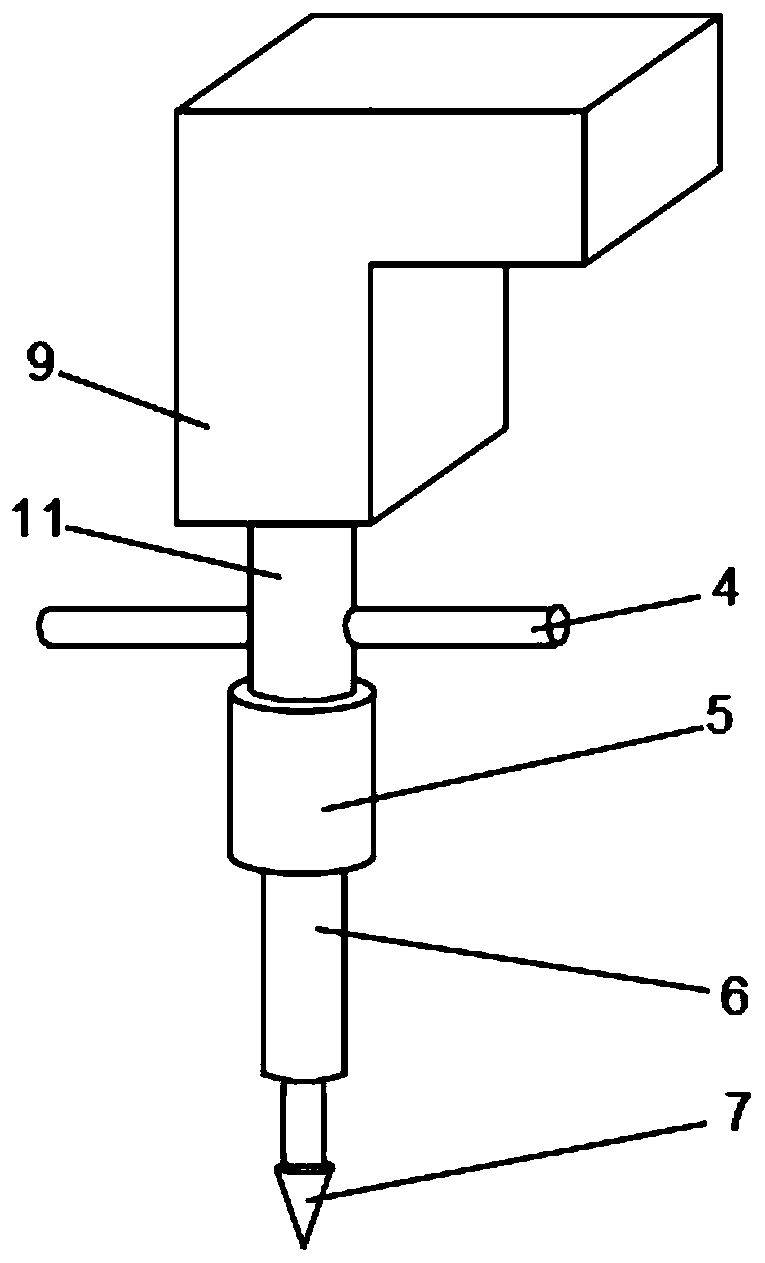
[0021] This embodiment provides an electric ground anchor hammering installation device, including a casing 9, the lower end of the casing 9 is connected with a sliding tube 11, the casing 9 and the sliding tube 11 are integrally formed and communicate with each other, and the sliding tube 11 is slidably connected with a A slider 3, a motor 1 and a gear box 8 are installed inside the housing 9, the output shaft of the motor 1 is fixedly connected to the input end of the gear box 8, and the output end of the gear box 8 is fixedly connected to a turntable 10, so The edge of the turntable 10 is rotatably connected to a connecting rod 2, the other end of the connecting rod 2 is rotatably connected to the slider 3, and the lower end of the slider 11 is slidably connected to a hammer 5, and a hammer 5 is provided below the hammer 5. There is a mounting rod 6, and a ground anchor 7 is arranged below the mounting rod 6.

[0022] When the device is working, the motor 1 rotates at a hig...

Embodiment 2

[0024] The electric ground anchor hammering installation device provided in this embodiment is basically the same as that in Embodiment 1, and the specific scheme is better.

[0025] This embodiment provides an electric ground anchor hammering installation device, including a casing 9, the lower end of the casing 9 is connected with a sliding tube 11, the casing 9 and the sliding tube 11 are integrally formed and communicate with each other, and the sliding tube 11 is slidably connected with a A slider 3, a motor 1 and a gear box 8 are installed inside the housing 9, the output shaft of the motor 1 is fixedly connected to the input end of the gear box 8, and the output end of the gear box 8 is fixedly connected to a turntable 10, so The edge of the turntable 10 is rotatably connected to a connecting rod 2, the other end of the connecting rod 2 is rotatably connected to the slider 3, and the lower end of the slider 11 is slidably connected to a hammer 5, and a hammer 5 is provid...


PUM


Abstract

The invention provides an electric ground anchor hammering installation device. The device comprises a shell, wherein the lower end of the shell is connected with a sliding cylinder, a sliding block is arranged in the sliding cylinder in a sliding mode, a motor and a gearbox are installed inside the shell, an output shaft of the motor is fixedly connected with the input end of the gearbox, the output end of the gearbox is fixedly connected with a rotating disc, the edge of the disc surface of the rotating disc is rotationally connected with a connecting rod, the other end of the connecting rodis connected to the sliding block in a rotating mode, the lower end of the sliding cylinder is connected with a driving hammer in a sliding mode, an installing rod is arranged under the driving hammer, and a ground anchor is arranged under the installing rod. According to the electric ground anchor hammering installation device, electric energy is used as power to install the ground anchor, by adopting the technical scheme, the manpower can be saved, the working efficiency can be improved, the electric energy can be adjusted as the power, the use is convenient and safe, and the electric ground anchor hammering installation device is suitable for different installation environments.

Description

technical field [0001] The invention relates to the field of installation and maintenance of electric power systems, and more particularly relates to an electric ground anchor hammering installation device. Background technique [0002] At present, agriculture, industry, and tourism in Guangdong Province have developed rapidly, and economic development has higher and higher requirements for power supply reliability of the power grid. However, typhoons frequently occur in the coastal areas, and the distribution network poles in the coastal areas of Guangdong are not strong enough to resist wind, threatening the local economic development. Therefore, it is necessary to strengthen the windproof poles of the distribution network lines in coastal areas. However, in the field construction, the ground anchors of the poles are installed by manual hammering, which is time-consuming and laborious, and the work efficiency is low. Contents of the invention [0003] The present invent...

Claims


Application Information

Patent Timeline
Patent Type & Authority Applications(China)
IPC IPC(8): B25D11/00B25D11/04
CPCB25D11/00B25D11/04
Inventor 夏志雄曾永浩黄荣林杨季艾维李亮明陈发培林金旋曾伟坚罗景雄
Owner GUANGDONG POWER GRID CO LTD
Why Eureka
Try Eureka