Voucher binding device and punching device

A punching device and voucher technology are applied in the directions of bookbinding, book binding, book binding and flattening machine, etc., which can solve the problems of low efficiency, the holes drilled are not neat and beautiful, and achieve a reasonable and simple structure, low production cost, The effect of improving efficiency

Inactive Publication Date: 2017-12-05
YANTAI POWER SUPPLY COMPANY OF STATE GRID SHANDONG ELECTRIC POWER +1
View PDF7 Cites 2 Cited by
  • Summary
  • Abstract
  • Description
  • Claims
  • Application Information

AI Technical Summary

Problems solved by technology

[0003] The purpose of the present invention is to provide a voucher binding device and a punching device in order to solve the above problems, which solves the problem that the existing voucher binding device needs to drill holes one by one. Not neat enough

Method used


Image

  • Voucher binding device and punching device
  • Voucher binding device and punching device
  • Voucher binding device and punching device

Examples


Embodiment Construction

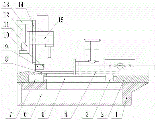
[0019] Such as figure 1 As shown, this specific embodiment adopts the following technical solutions: a voucher binding device, including a base 1, a frame 2, a nut seat 3, a voucher pressing device 4, a screw 5, a collection box 6, a motor 7, a transverse guide rail 8, Limit block 9, limit switch 10, connection block 11, oil cylinder 12, fixed block 13, vertical guide rail 14 and punching device 15; the bottom of frame 2 is fixedly connected to base 1, and the lower side of frame 2 is provided with a horizontal Guide rail 8, the left side of frame 2 is provided with vertical guide rail 14; Collecting box 6 is movably connected on the left side inside base 1; The lower side of credential pressing device 4 is movably connected on the horizontal guide rail 8, and the center of the bottom surface of credential pressing device 4 It is fixedly connected with the top surface of the nut seat 3; the nut seat 3 is movably connected to the top of the screw rod 5; the screw rod 5 is movab...


PUM


Abstract

The invention discloses a voucher binding device which comprises a base, a frame, a nut seat, a voucher pressing device, a screw rod, a collecting box, a motor, a transverse guide rail, a limit block, a limit switch, a connecting block, an oil cylinder, a fixing block, a vertical guide and a punching device. The punching device includes a vertical movable seat, a gear box I, a drill chuck, a drill, a gear box II, a driven gear, a driving gear, a drilling motor, a gear I, a gear II, a gear III, a gear IV, a gear five V, a gear VI and a gear VII. The voucher binding device has the advantages of reasonable structure and simple structure, low production cost and convenient installation, improves the efficiency of drilling, and also ensures the quality after the drilling, and finally vouchers are bound by needlework or glue.

Description

technical field [0001] The invention relates to the technical field of binding devices, in particular to a voucher binding device and a punching device. Background technique [0002] Binding of paper-based financial accounting vouchers requires the use of accounting voucher binding equipment. The existing accounting voucher binding equipment is actually a drilling device. The financial personnel arrange the vouchers and place them on the machine base of the drilling device. After the device is drilled, use needle thread or glue to bind it. This method is cumbersome to organize. Especially when drilling, it needs to be drilled hole by hole, which is not only inefficient, but also the drilled holes are not neat and beautiful. Contents of the invention [0003] The purpose of the present invention is to provide a voucher binding device and a punching device in order to solve the above problems, which solves the problem that the existing voucher binding device needs to drill h...

Claims


Application Information

Patent Timeline
IPC IPC(8): B42C13/00B42B5/02B42B2/02B42C9/00
CPCB42B2/02B42B5/02B42C9/00B42C13/00
Inventor 于洋安好好孙建涛王芳郑伟刘国强于航高阳张一荻孙丽赵晓洁崔腾孙伟伟申凯玮王江华
Owner YANTAI POWER SUPPLY COMPANY OF STATE GRID SHANDONG ELECTRIC POWER
Why Eureka
Try Eureka