Novel punching mold

A stamping die, a new type of technology, applied in the direction of forming tools, manufacturing tools, metal processing equipment, etc., can solve the problem of different pressing depth of the mold, affecting the stamping effect, etc., to achieve good stamping effect, consistent pressing depth, and upper mold. force balance effect

Active Publication Date: 2019-12-17
DAYE ZD TOOLING CO LTD
6 Cites 1 Cited by

AI-Extracted Technical Summary

Problems solved by technology

[0003] In the process of pressing down the upper mold of the existing stamping die, due to the gaps inside the guide columns or spring columns on both sides, ...

Abstract

The invention relates to a novel punching mold. The novel punching mold comprises an upper mold bracket and a lower mold bracket; an upper mold and two upper columns are mounted on the lower side of the upper mold bracket; a lower mold and two lower columns are mounted on the upper side of the lower mold bracket; the lower columns are embedded in the upper columns; transmission devices are mountedon the left sides of the two upper columns, and comprise first racks; first gears are arranged on the left sides of the first racks, and are engaged with the first racks; second gears and third gearsare arranged on the lower sides of the first gears; the second gears are engaged with the first gears and the third gears; two cavities are formed in the lower mold bracket; slide rails are fixed inthe two cavities, and are slidingly connected with second racks; the second racks are engaged with the third gears; and a push rod is connected between the two second racks. The novel punching mold isexcellent in punching effect.

Application Domain

Shaping tools

Technology Topic

EngineeringPunching +1

Image

  • Novel punching mold
  • Novel punching mold
  • Novel punching mold

Examples

  • Experimental program(1)

Example Embodiment

[0020] The principles and features of the present invention will be described below with reference to the accompanying drawings. The examples cited are only used to explain the present invention, and are not used to limit the scope of the present invention.
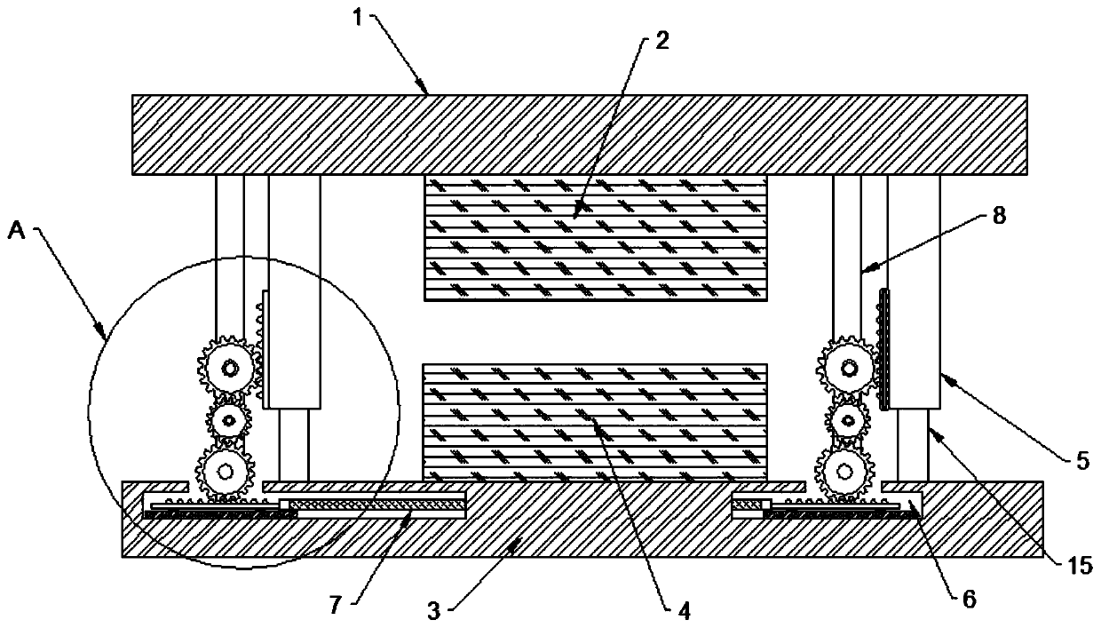
[0021] Such as figure 1 As shown, a new type of stamping die includes an upper mold bracket 1, a lower mold bracket 3. The upper mold bracket 1 is equipped with an upper mold 2, two upper posts 5, and the two upper posts 5 are located on two sides of the upper die 2. side. The upper side of the lower mold bracket 3 is equipped with a lower mold 4 and two lower pillars 15. The lower pillar 15 is embedded in the upper pillar 5, and the lower pillar 15 is slidably connected to the upper pillar 5, and the two upper pillars 5 are also embedded inside With the spring, the lower post 15 abuts against the spring.
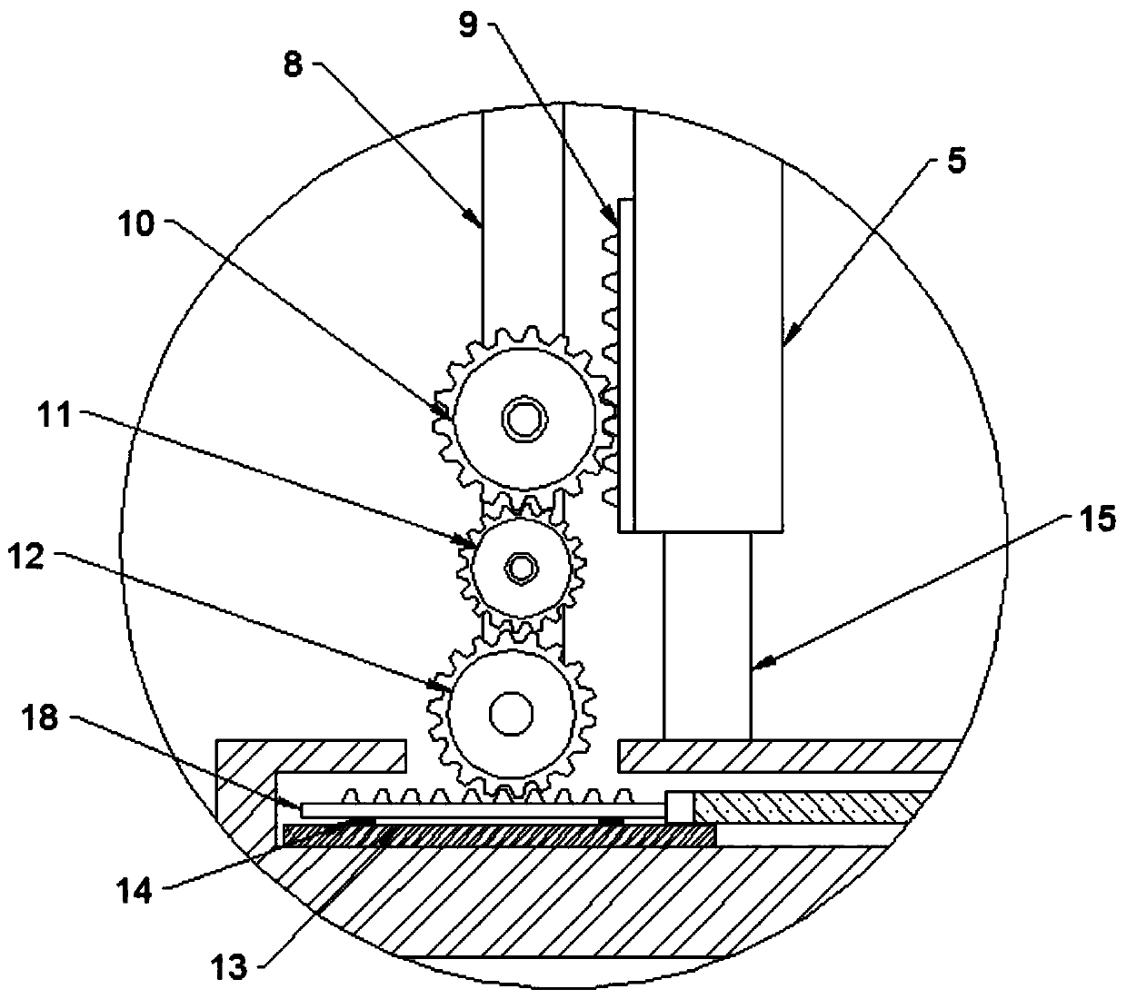
[0022] Such as figure 1 , figure 2 , image 3 , Figure 4 As shown, a transmission device is installed on the left side of each upper column 5, and the transmission device includes a first rack 9, and the left side of the first rack 9 is provided with a first gear 10, the first gear 10 and the first rack 9 meshing. A second gear 11 and a third gear 12 are provided on the lower side of the first gear 10, and the second gear 11 meshes with the first gear 10 and the third gear 12, respectively. Two gear mounting plates 8 are also fixed on the lower side of the upper mold support 1, and the first gear 10, the second gear 11, and the third gear 12 are all fixed on the gear mounting plate 8. The lower mold bracket 3 is provided with two cavities 6 inside, and slide rails 13 are fixed inside the two cavities 6, and a second rack 18 is slidably connected to the slide rail 13, specifically, the slide rail 13 and the second rack A slider 14 is connected between the racks 18. The second rack 18 meshes with the third gear 12, and a push rod 7 is connected between the two second racks 18. Both ends of the push rod 7 are provided with threaded holes 17, and the second rack 18 and the push rod 7 are fixedly connected by threads. A circular hole 16 is provided inside the lower mold bracket 3, and the push rod 7 passes through the inside of the circular hole 16. When the upper mold bracket 1 is pressed down, the two first racks 9 move down, driving the first gear 10 to rotate clockwise. At this time, the second gear 11 rotates counterclockwise, and when the second gear 11 rotates, the third gear 12 rotates clockwise. Turning, the third gear 12 drives the second rack 18 to move to the left.
[0023] When using this new type of stamping die, the upper die bracket 1 is pressed down, and the two first racks 9 move down, driving the first gear 10 to rotate clockwise. At this time, the second gear 11 rotates counterclockwise, and the second gear 11 rotates. The third gear 12 rotates clockwise, and the third gear 12 drives the second rack 18 to move to the left. Because the push rod 7 is connected between the two second racks 18, it passes when the left and right upper posts 5 move at different depths. The push rod 7 is linked, and the second rack 18 on both sides moves the same distance during linkage. The transmission of each gear can ensure that the first rack 9 on both sides moves down the same distance, thereby ensuring the depth of the depression of the two upper posts 5 Consistent, the upper die 2 has a balanced force. The punching effect is better when the upper die 2 is balanced in force. The new stamping die has good stamping effect.
[0024] The above descriptions are only preferred embodiments of the present invention and are not intended to limit the present invention. Any modification, equivalent replacement, improvement, etc. made within the spirit and principle of the present invention shall be included in the protection of the present invention. Within range.

PUM

no PUM

Description & Claims & Application Information

We can also present the details of the Description, Claims and Application information to help users get a comprehensive understanding of the technical details of the patent, such as background art, summary of invention, brief description of drawings, description of embodiments, and other original content. On the other hand, users can also determine the specific scope of protection of the technology through the list of claims; as well as understand the changes in the life cycle of the technology with the presentation of the patent timeline. Login to view more.

Similar technology patents

Metal plate stamping die

InactiveCN104384344Aavoid breakingGood stamping effect
Owner:吴中区光福华宇钣金厂

Stamper punch for punching

ActiveCN103639277AEasy to installGood stamping effect
Owner:东莞市鹏隆实业有限公司
Why Eureka
Try Eureka