
Keyboard

A keyboard and key technology, applied in the field of input devices, can solve the problems of severe key caps, such as touch feeling, bad touch, damage, etc.

Inactive Publication Date: 2019-12-17
PRIMAX ELECTRONICS LTD
View PDF5 Cites 0 Cited by
  • Summary
  • Abstract
  • Description
  • Claims
  • Application Information

AI Technical Summary

Problems solved by technology

In fact, the assembled sliding hook and the first connecting portion will still be damaged due to wear and tear, and the damage is still serious enough to cause poor touch and feel of the key cap

Method used


Image

  • Keyboard
  • Keyboard
  • Keyboard

Examples


Embodiment Construction

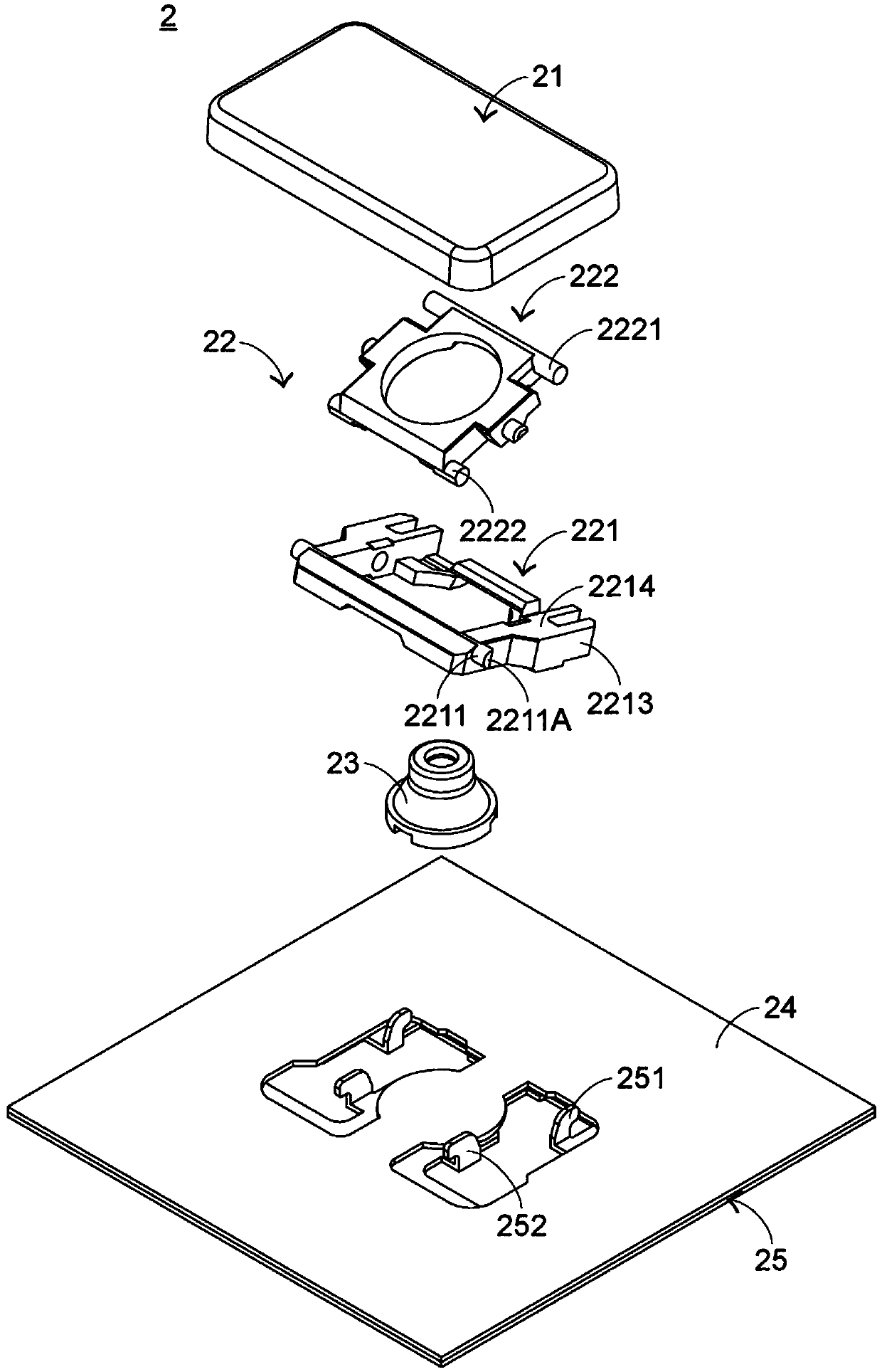
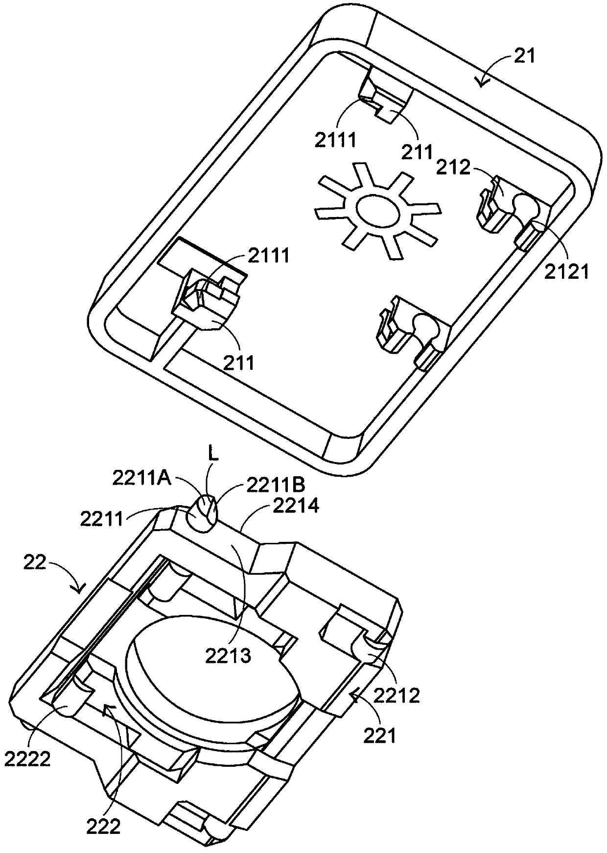
[0048] In view of the problems caused by the known technology, the present invention provides a keyboard that can solve the problems of the known technology. First illustrate the structure of the keyboard of the present invention, please refer to figure 2 as well as image 3 , figure 2 It is an exploded schematic diagram of a partial structure of the keyboard of the present invention in a preferred embodiment, and image 3It is an exploded schematic diagram of the structure of keycaps and connecting elements of the keyboard of the present invention from another perspective in a preferred embodiment. The keyboard 2 of the present invention includes a plurality of keycaps 21 (only one is shown in the figure), connecting elements 22 (only one is shown in the figure), elastic elements 23 (only one is shown in the figure), a switch circuit board 24 and a bottom plate 25 . The key cap 21 is exposed outside the keyboard 2, and the key cap 21 includes a sliding hook 211 and a fix...


PUM


Abstract

The invention provides a keyboard, which comprises a key cap with a sliding hook, a connecting element and a bottom plate, wherein the connecting element comprises a first frame and a second frame, and a first connecting part of the first frame extends into the sliding hook. The first connecting part comprises a top surface and a contact slope, wherein the top surface is located at the tail end ofthe first connecting part, and the contact slope is adjacent to the top surface. The boundary line of the top surface and the contact slope is perpendicular to the upper surface of the first frame. The contact area between the first connecting part and the sliding hook can be reduced through the structure of the contact slope, so that the assembly interference amount between the first connectingpart and the sliding hook can be reduced.

Description

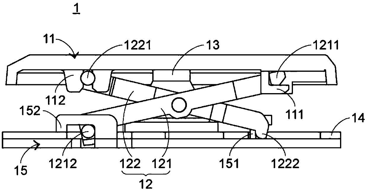
technical field [0001] The invention relates to an input device, in particular to a keyboard with a plurality of keys. Background technique [0002] Common computer peripheral input devices include a mouse, a keyboard, and a trackball. The keyboard can directly input text and symbols to the computer, so it is highly valued by users and input device manufacturers. The subject of the present invention is the keyboard. [0003] Next, the partial structure of the keyboard including the scissor-type connecting elements will be described. see figure 1 , which is a schematic partial cross-sectional side view of a known keyboard. The known keyboard 1 includes a plurality of keycaps 11 (only one is shown in the figure), a plurality of scissor-type connecting elements 12 (only one is shown in the figure), a plurality of elastic rubber bodies 13 (only one is shown in the figure), a membrane switch circuit 14 And the bottom plate 15 , and the bottom plate 15 is used to carry the key...

Claims


Application Information

Patent Timeline
IPC IPC(8): H01H13/12H01H13/20H01H13/85H01H3/12
CPCH01H3/125H01H13/12H01H13/20H01H13/85H01H2215/00
Inventor 凌郁婷徐百平郑祥文
Owner PRIMAX ELECTRONICS LTD
Learn More