A radiotherapy system alarm circuit

An alarm circuit and radiotherapy technology, which is applied in the field of radiotherapy system alarm circuit, can solve problems such as not being able to notify medical staff in time, and achieve the effect of ensuring medical safety

Active Publication Date: 2021-02-05
QINGDAO MUNICIPAL HOSPITAL
View PDF8 Cites 0 Cited by
  • Summary
  • Abstract
  • Description
  • Claims
  • Application Information

AI Technical Summary

Problems solved by technology

[0003] In order to overcome the shortcomings of the current patients who are undergoing radiation therapy, when adverse reactions occur, the medical staff cannot be notified in time due to the body position fixing device, the technical problem of the present invention is: to provide a method that can combine the alarm system with the LED display screen, which can be used in patients. The radiation therapy system alarm circuit that reminds medical staff in time of adverse reactions

Method used


Image

  • A radiotherapy system alarm circuit
  • A radiotherapy system alarm circuit

Examples


Embodiment 1

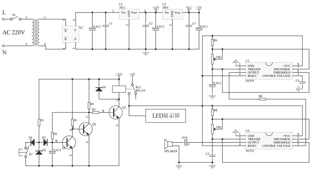
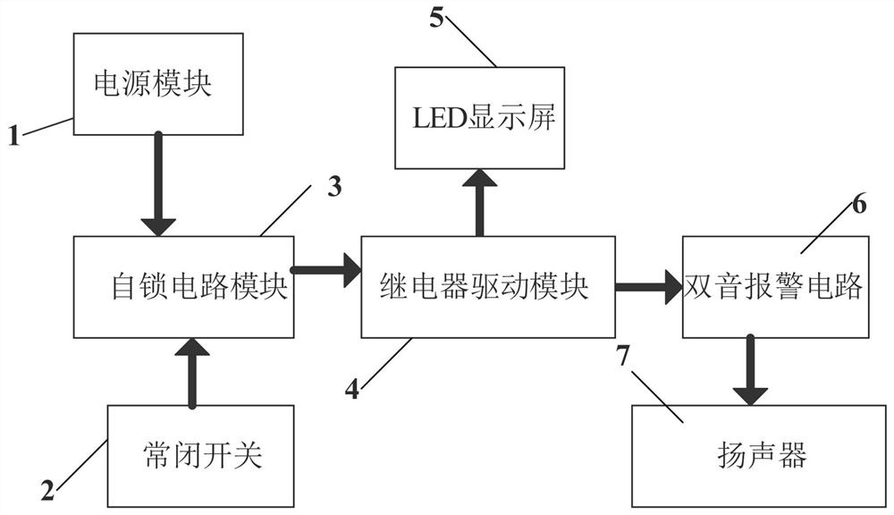
[0017]An alarm circuit for radiotherapy system, such asFigure 1-2As shown, it includes a power supply module 1, a normally closed switch 2, a self-locking circuit module 3, a relay drive module 4, and an LED display screen 5. The output end of the normally closed switch 2 is connected to the input end of the self-locking circuit module 3. The output end of the self-locking circuit module 3 is connected to the input end of the relay drive module 4. The self-locking circuit module 3 is used to control the operation of the relay drive module 4, and the output end of the relay drive module 4 is connected to the LED display screen 5. The LED display screen 5 can display related information and warning words, and the power supply module 1 is a normally closed switch 2, a self-locking circuit module 3, a relay drive module 4, and an LED display screen 5 to supply power.

[0018]The self-locking circuit module 3 includes resistors R1, R2, R3, R4, transistors Q1, Q2, electrolytic capacitors EC4...

Embodiment 2

[0022]An alarm circuit for radiotherapy system, such asfigure 1 As shown, it also includes a dual-tone alarm circuit 6 and a speaker 7. The output end of the relay drive module 4 is connected to the input end of the dual-tone alarm circuit 6, and the relay drive module 4 is used to switch the dual-tone alarm circuit 6. The output end of the dual-tone alarm circuit 6 is connected to a speaker 7, and the frequency of the speaker 7 can be set by the dual-tone alarm circuit 6. The power supply module 1 supplies power for the dual-tone alarm circuit 6 and the speaker 7.

[0023]After the alarm circuit is powered on, when the patient presses the normally closed switch 2, when the output of the self-locking circuit module 3 is high, the relay drive module 4 works and drives the LED display 5 to work, and the LED display 5 displays patient information, dual tone The alarm circuit 6 drives the loudspeaker 7 to work, informs the medical staff in time, and responds accordingly. Until the switch S...

Embodiment 3

[0025]An alarm circuit for radiotherapy system, such asfigure 2 As shown, the dual-tone alarm circuit 6 is composed of a first-stage multivibrator and a second-stage multivibrator. The first-stage multivibrator includes NE555 U3, potentiometer VR1, resistor R6, and capacitor C4. And electrolytic capacitor EC5, one end of the resistor R6 is connected to the NO terminal of the relay RL1, the other end of the resistor R6 is connected to one end and the output end of the potentiometer VR1, the other end of the potentiometer VR1 is connected to one end of the electrolytic capacitor EC5, so The other end of the electrolytic capacitor EC5 is grounded; the DISCHARGE pin of the NE555 U3 is connected to the other end of the resistor R6, and the THRESHOLD pin of the NE555 U3 is connected to the connection point between the other end of the potentiometer VR1 and one end of the electrolytic capacitor EC5, so The +VCC pin of the NE555 is connected to the NO terminal of the relay RL1, the GND pin ...


PUM


Abstract

The invention relates to the technical field of treatment instruments, in particular to a radiotherapy system alarm circuit. The technical problem of the invention is to provide a radiotherapy systemalarm circuit which can combine an alarm system with an LED display screen and can remind medical staff in time when a patient has an adverse reaction. The radiotherapy system alarm circuit comprisesa normally-closed switch, a self-locking circuit module, a relay driving module and the like. The output end of the normally-closed switch is connected with the input end of the self-locking circuit module, and the output end of the self-locking circuit module is connected with the input end of the relay driving module. When a patient receives radiotherapy and generates adverse reaction, an alarmsignal can be sent out in time through the normally-closed switch controlled by the hand, the alarm signal is processed through the self-locking circuit module, the LED display screen, the double-tonealarm circuit, the alarm content displayed by the LED display screen and the loudspeaker are driven to give an alarm, and medical safety is guaranteed.

Description

Technical field[0001]The invention relates to the technical field of therapeutic instruments, and relates to an alarm circuit of a radiotherapy system.Background technique[0002]Tumor radiotherapy is a local treatment method that uses radiation to treat tumors. Radiation includes alpha, beta, and gamma rays produced by radioisotopes and x-rays, electron rays, proton beams and other particle beams produced by various x-ray treatment machines or accelerators. Approximately 70% of cancer patients need radiotherapy during the treatment of cancer, and about 40% of cancers can be cured with radiotherapy. The role and status of radiotherapy in tumor treatment have become increasingly prominent, and it has become one of the main methods for the treatment of malignant tumors. The curative effect of radiotherapy depends on the sensitivity of radiation. Different tissues and organs and various tumor tissues have different response degrees after being irradiated. Radiosensitivity is related to t...

Claims


Application Information

Patent Timeline
Patent Type & Authority Patents(China)
IPC IPC(8): H04M11/02A61N5/10
CPCA61N5/1001H04M11/027
Inventor 徐晓妹王萍崔新景田赛周操操
Owner QINGDAO MUNICIPAL HOSPITAL
Why Eureka
Try Eureka