Bottom pouring steel ladle

A technology of ladle and bottom injection, which is applied in the direction of casting molten material containers, metal processing equipment, casting equipment, etc., can solve the problems of inconvenient operation for workers, and achieve the effect of improved safety and convenient operation

Inactive Publication Date: 2019-12-20
湖北八环机械科技有限公司
View PDF0 Cites 1 Cited by
  • Summary
  • Abstract
  • Description
  • Claims
  • Application Information

AI Technical Summary

Problems solved by technology

[0003] The purpose of this invention is to solve the problem that the operating lever of the operating mechanism of the existing bottom injection ladle is arranged in a fixed direction, which is very inconvenient for workers in actual operation, and to provide a bottom injection ladle that can be operated at any angle

Method used


Image

  • Bottom pouring steel ladle
  • Bottom pouring steel ladle
  • Bottom pouring steel ladle

Examples


Embodiment Construction

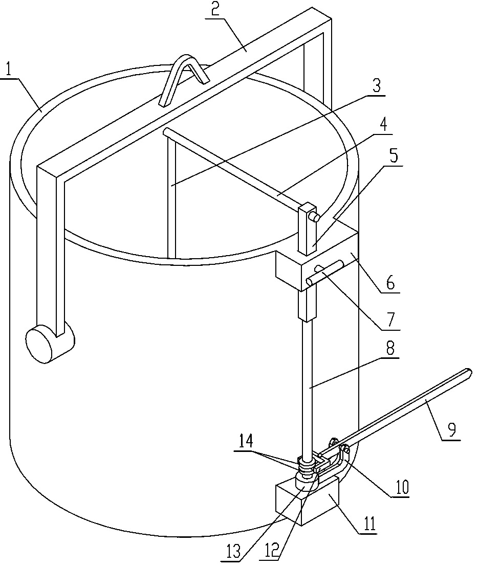
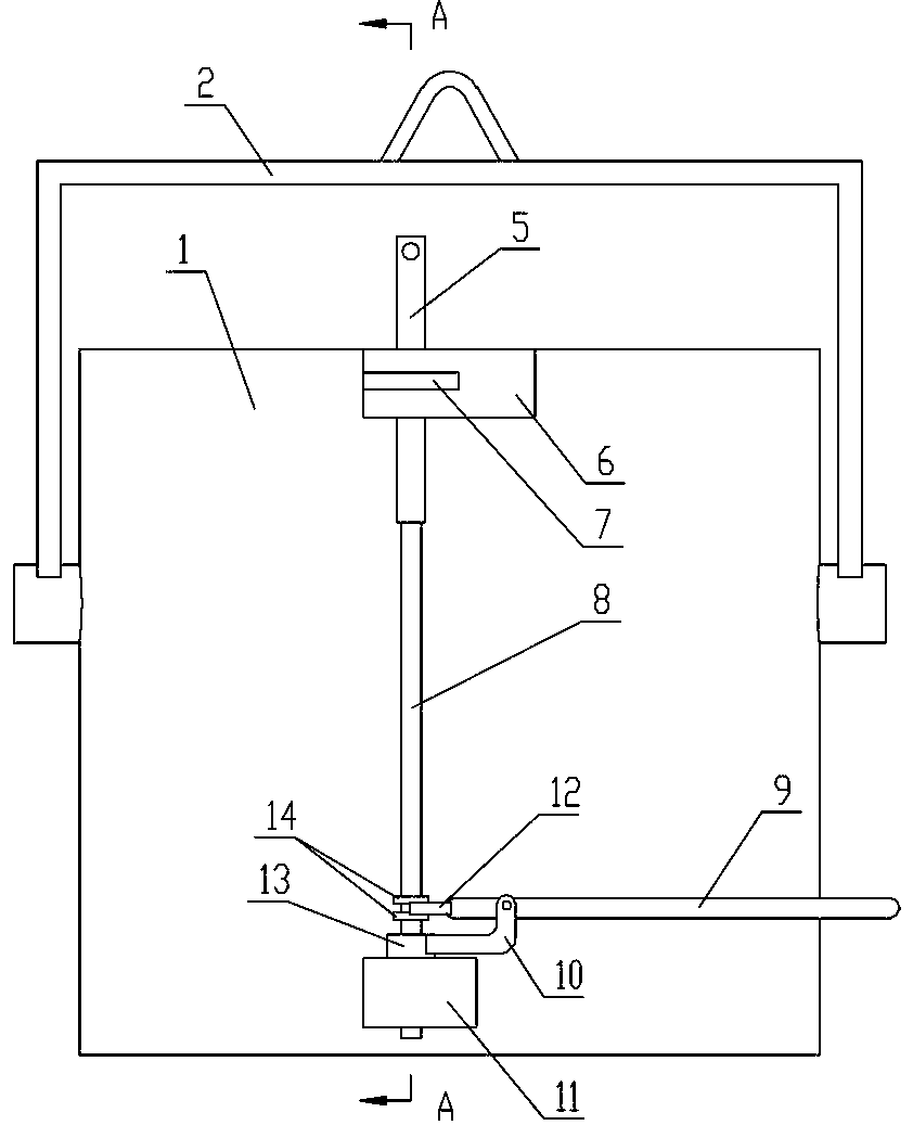
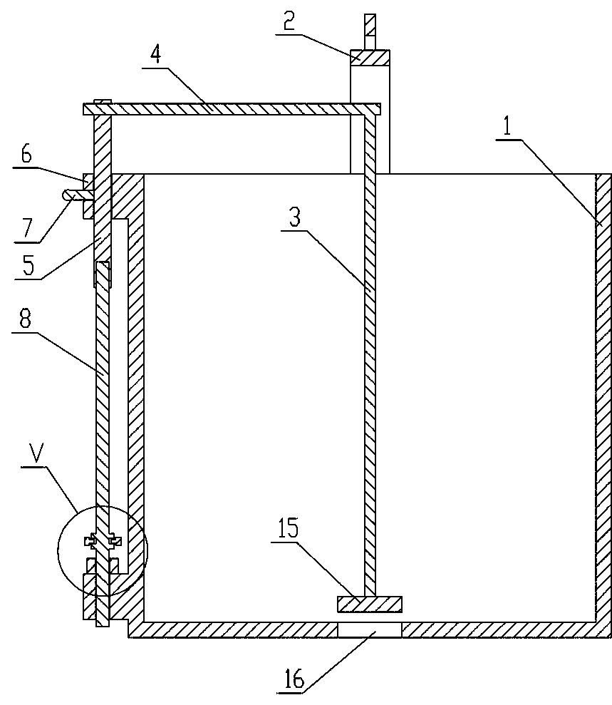
[0012] see Figure 1-4 , the present embodiment comprises a gantry 2, the two ends of the gantry 2 are provided with vertically downward support plates, a ladle 1 is arranged between the two support plates, a pouring hole 16 is provided at the bottom of the ladle 1, and a pouring hole 16 is installed above the pouring hole 16. There is a sealing plate 15, and a set of lifting device is connected to the top of the sealing plate 15. The lifting device includes a support plate A11 fixed on the lower part of the outer wall of the ladle 1. The ladle 1 is fixed above the support plate A11 with a rectangular The support plate B6 of the through hole, a circular through hole is arranged in the middle of the support plate A11, a collar 13 is arranged above the circular through hole, and a vertical cylindrical ejector rod 8 is housed in the collar 13, and the ejector rod 8 The bottom passes through the circular through hole of the support plate A11, and a bracket 10 is fixedly installed ...


PUM


Abstract

The invention discloses a bottom pouring steel ladle. The steel ladle involves a portal frame, wherein the steel ladle is arranged on the portal frame, a pouring hole is formed in the bottom of the steel ladle, a sealing plate is arranged above the pouring hole, and the top of the sealing plate is connected with a set of lifting device; the lifting device comprises a support plate A fixed to the outer wall of the steel ladle, a support plate B is arranged above the support plate A, a circular through hole is formed in the middle of the support plate A, a collar is arranged above the circular through hole, a push rod is arranged in the collar, and the bottom of the push rod passes through the circular through hole of the support plate A; a support is arranged on the outer wall of the collar, an operation rod is hinged to the tail end of the support, one end of the operation rod is arranged in a suspending mode, two parallel branch rods are arranged at the other end of the operation rod,each of the two branch rods is provided with a sliding column, the two sliding columns are just located on the two sides of the push rod correspondingly, a baffle is arranged on the part, located oneach of the upper surface and the lower surface of each sliding column, of the push rod, the top of the push rod passes through the support B to be provided with a supporting rod, the supporting rod is provided with a downward extending connecting rod, and the bottom of the connecting rod is connected with the sealing plate. The bottom pouring steel ladle realizes the operation at any angle.

Description

technical field [0001] The invention relates to the field of steelmaking equipment, in particular to a bottom injection type molten steel ladle. Background technique [0002] At present, the bottom injection ladle is widely used in steelmaking equipment. The traditional bottom injection ladle structure is that there is a sprue at the bottom of the ladle, and a sealing plate is set above the sprue. The sealing plate is driven by the operating mechanism installed outside the ladle. Lifting to complete the pouring action, while the operating lever of the operating mechanism of the general bottom pouring ladle is arranged in a fixed direction. In the actual use process, the site environment is different, and the operating lever fixed in one direction is very inconvenient for the actual operation of the workers. convenient. Contents of the invention [0003] The purpose of this invention is to solve the problem that the operating lever of the operating mechanism of the existin...

Claims


Application Information

Patent Timeline
Patent Type & Authority Applications(China)
IPC IPC(8): B22D41/14
CPCB22D41/14
Inventor 陈国清
Owner 湖北八环机械科技有限公司
Why Eureka
Try Eureka