Mitre cut sawing machine

A sawing machine and bevel cutting technology, applied in the field of sawing machines, can solve the problem of unresolved clamping problems of clamps, etc.

Active Publication Date: 2019-12-20
KEURO BESITZ & EDV DIENSTLEISTUNGS
View PDF13 Cites 4 Cited by
  • Summary
  • Abstract
  • Description
  • Claims
  • Application Information

AI Technical Summary

Problems solved by technology

The problem of asymmetrical clamping of the slope in the vise when sawing particularly gentle miter angles remains unresolved here

Method used


Image

  • Mitre cut sawing machine
  • Mitre cut sawing machine
  • Mitre cut sawing machine

Examples


Embodiment Construction

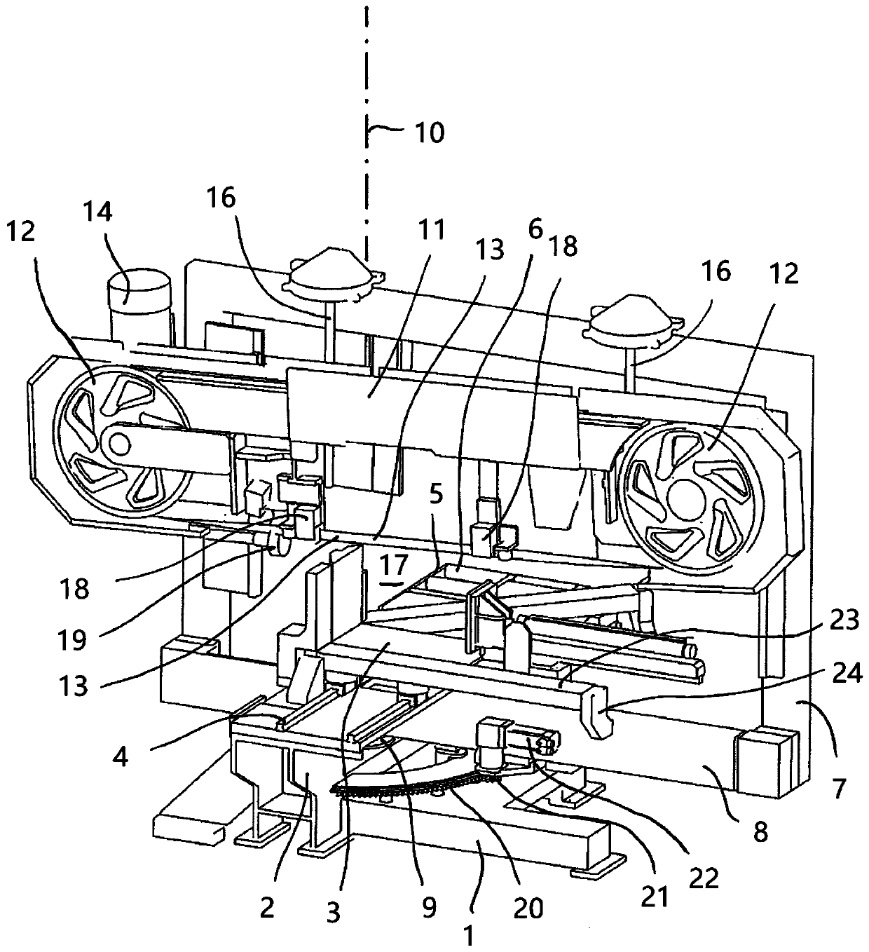
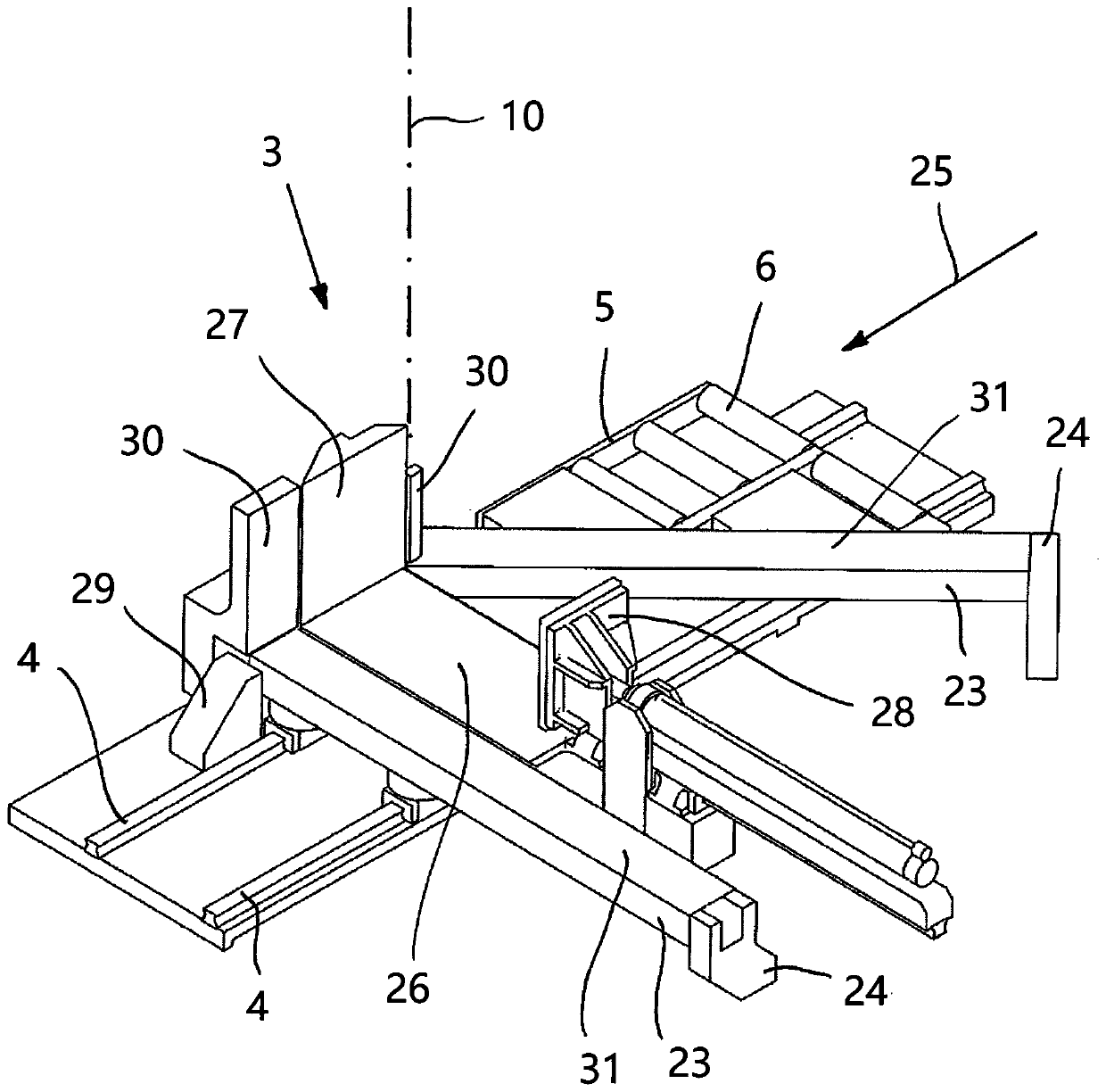
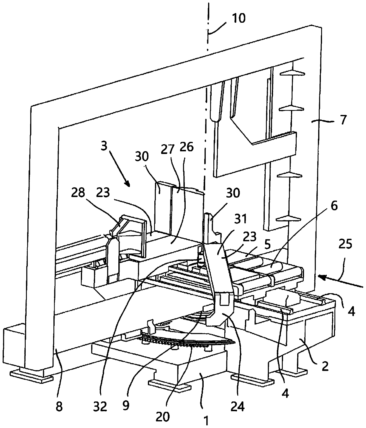
[0058] In order to better understand the housing and accessories omitted here of the present invention, figure 1 An embodiment of a sawing machine designed according to the invention for mitering metal workpieces is shown in a schematic perspective view, comprising a stationary base 1 with a support for a sawing table 3 The seat 2 and the sawing table 3 can move along the two rails 4 on the support 2. In this illustration, the infeed side of the sawing machine is located at the rear, on which infeed side the infeed raceway 6 is fastened to the support 2 of the base 1 as the conveying path 5 .

[0059] On the base 1, a bracket 7 is pivotably fixed on the base 1 in the form of a frame, here the lower beam 8 of the bracket 7 cooperates for this purpose with a pin in a radial bearing 9 (not visible) and can The straight axis 10 pivots.

[0060] The support 7 carries the saw upper part 11 , which has two running wheels 12 around which the saw band 13 runs continuously. exist fi...


PUM


Abstract

A sawing machine for bevel cuts having an upper saw portion with two running wheels, one of which is motor driven, a saw band which rotates about the running wheels, a lifting and lowering device forthe upward and downward movement of the upper saw portion to move the saw band with a sawing advance movement in a sawing region, a transport path for supplying a workpiece in a supply direction to the sawing region, a frame, on which the upper saw portion is retained and which is pivotable about a vertical axis in order to adjust a bevel angle between the saw band and the supply direction. A movable sawing table is arranged in the sawing region for positioning the workpiece to be sawn and a clamping vice for clamping the workpiece during the sawing operation. The sawing table and the clampingvice are constructed to be movable in and counter to the supply direction.

Description

technical field [0001] The invention relates to a sawing machine for mitering metal workpieces according to the preamble of claim 1 . Such a sawing machine comprises a saw top in which a saw band is wound around at least two impellers, at least one of which is driven by an electric motor. In addition, the sawing machine also includes: a lifting device for raising and lowering the upper part of the sawing machine, so that the sawing band can be moved with a sawing feed movement in the sawing area, that is to say, when the sawing band is running, it can be threaded. Cutting motion over the workpiece to be sawed. Here the lifting device may be a device for translational movement of the upper part of the saw machine up and down; but within the scope of the present invention, the lifting device may also be a device for pivoting the upper part of the saw machine around a substantially horizontal axis, by This enables an up and down rotational movement of the saw band in the sawing...

Claims


Application Information

Patent Timeline
Patent Type & Authority Applications(China)
IPC IPC(8): B23D53/00B23D53/04B23D55/02B23D55/04B23D55/06B23D55/08
CPCB23D53/006B23D53/04B23D55/02B23D55/04B23D55/065B23D55/088B23D53/045B23D53/06B23D55/086Y10T83/7214
Inventor A·斯托泽S·F·克莱伯
Owner KEURO BESITZ & EDV DIENSTLEISTUNGS
Why Eureka
Try Eureka