Threading clamp

A threading jig and axis technology, applied in manufacturing tools, metal processing, metal processing equipment, etc., can solve the problems of reduced production capacity, long time-consuming manual threading, etc., and achieve the effect of convenient adjustment

Pending Publication Date: 2019-12-20
GUANGDONG LYRIC ROBOT INTELLIGENT AUTOMATION CO LTD
View PDF0 Cites 1 Cited by
  • Summary
  • Abstract
  • Description
  • Claims
  • Application Information

AI Technical Summary

Problems solved by technology

[0004] The purpose of this application is to provide a threading fixture, which can improve the ...

Method used


Image

  • Threading clamp
  • Threading clamp
  • Threading clamp

Examples


Embodiment

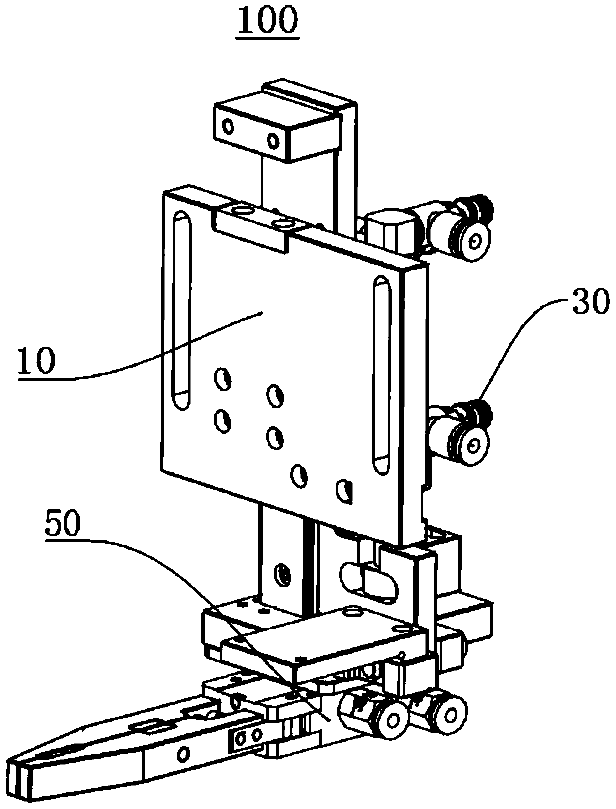
[0044] Please refer to Figure 1 to Figure 9 , the embodiment of the present application provides a threading fixture 100, including a first base 10, a driving mechanism 30 and a clamping device 50;

[0045] The driving mechanism 30 is arranged on the first base 10, and the clamping device 50 is connected to the output end of the driving mechanism 30. The clamping device 50 is used to clamp the thread to be threaded. The driving mechanism 30 can drive the clamping device 50 to translate and rotate.

[0046] Wherein, the threading clamp 100 can rely on the clamping device 50 to clamp and fix the thread to be threaded, and then realize the bending and movement of the thread to be threaded through the driving mechanism 30, thereby eliminating the need for manual threading and solving corresponding problems.

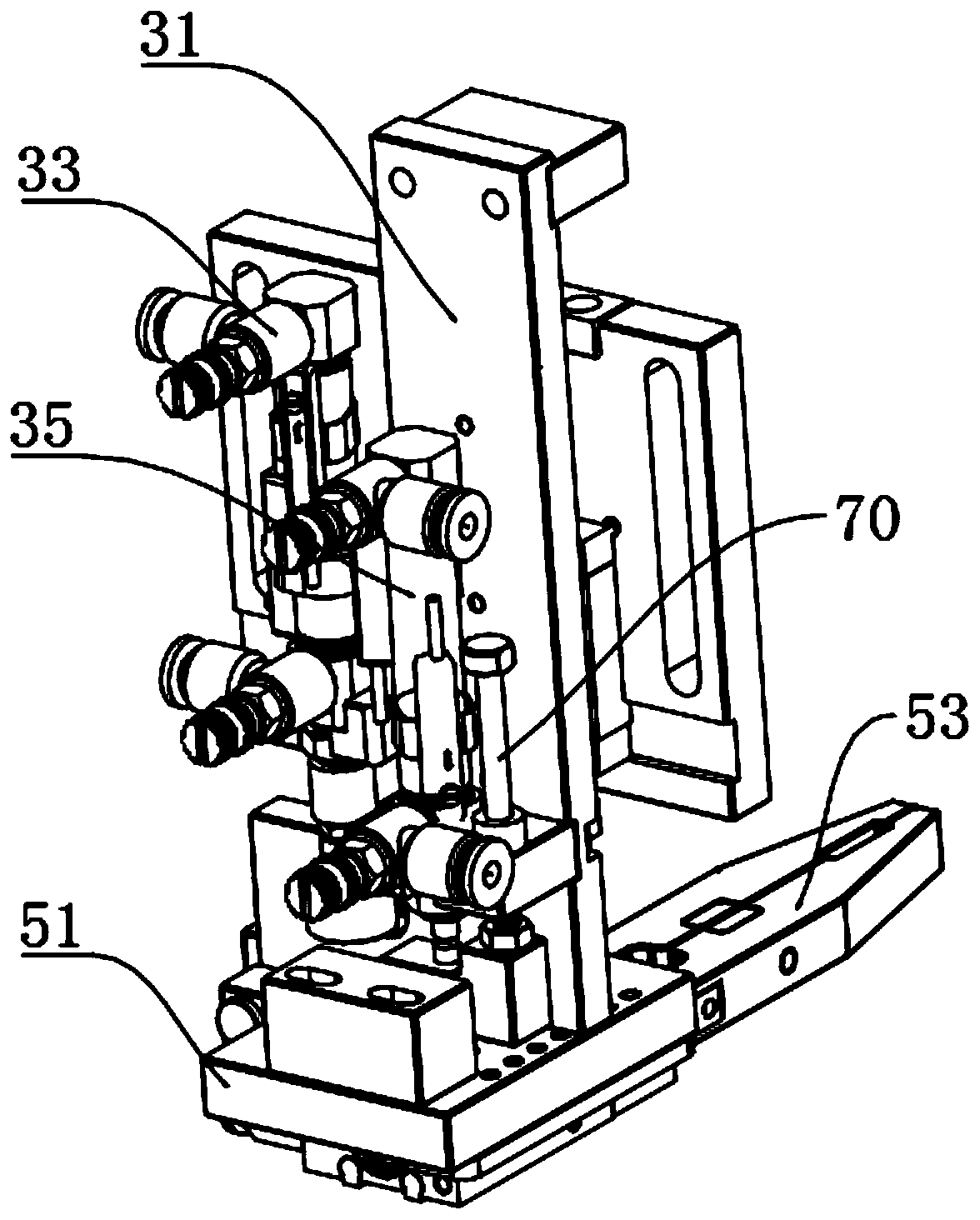
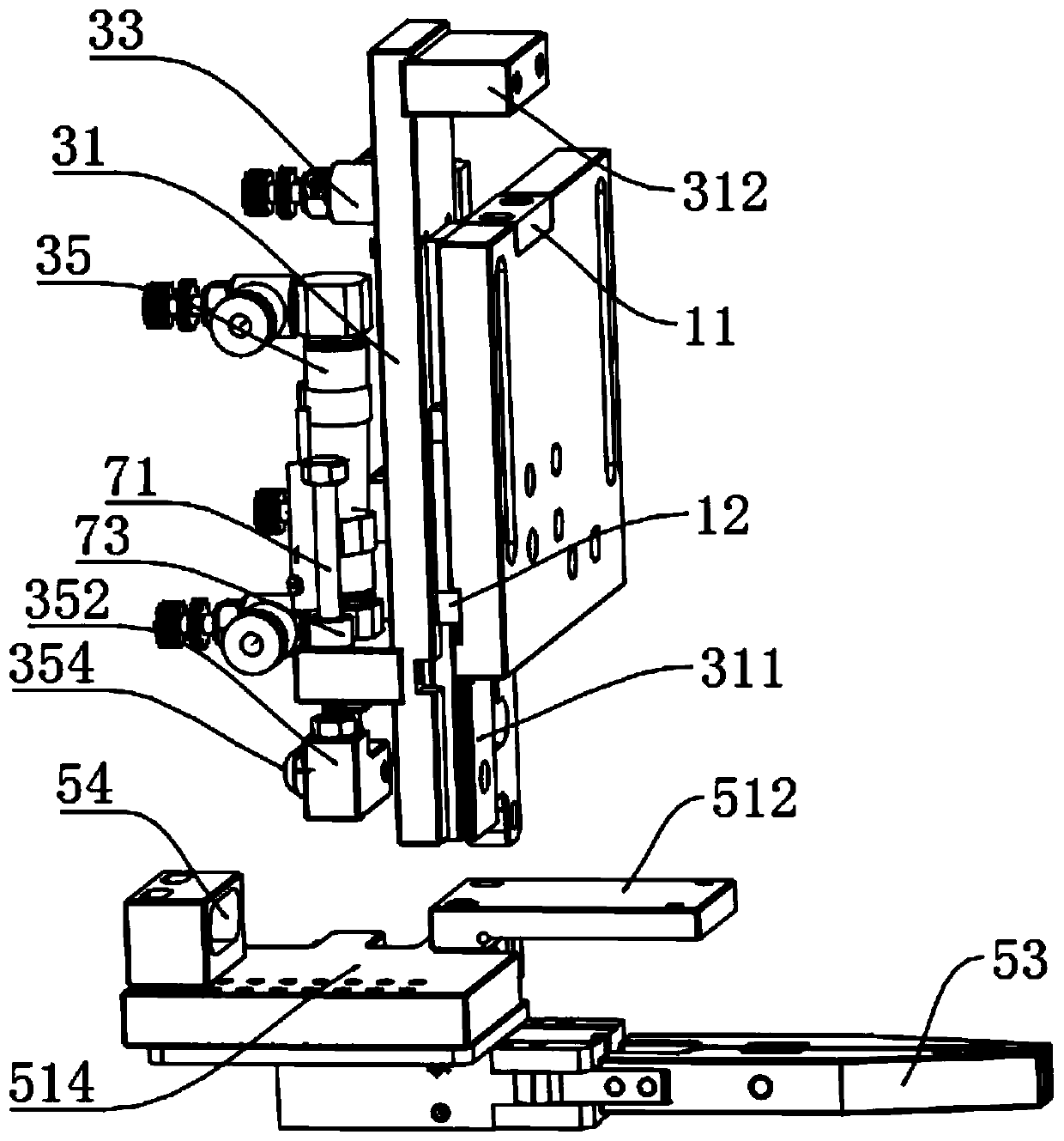
[0047] Please combine figure 2 and Figure 4Specifically, in this embodiment, the driving mechanism 30 includes a second base 31, a first driving device 33 and a second d...


PUM


Abstract

The invention provides a threading clamp, and relates to the technical field of clamps. The threading clamp comprises a first base, a driving mechanism and a clamping device, the driving mechanism isarranged on the first base, the clamping device is connected to the output end of the driving mechanism, the clamping device is used for clamping an object to be threaded, and the driving mechanism can drive the clamping device to translate and rotate. The driving mechanism of the threading clamp can drive the clamping device to translate or rotate, so that the flat cable clamped by the clamping device can be bent and translated, so as to complete the threading work, and compared with manual threading, the efficiency of threading is significantly improved.

Description

technical field [0001] The present application relates to the technical field of clamps, in particular, to a threading clamp. Background technique [0002] During the assembly process, there are situations where the assembly has a cable or other connecting wires, and it is necessary to thread the cable or connecting wire through the assembly to be assembled before assembling. The conventional practice in the industry is to arrange and assemble the equipment after manual bending or vertical insertion. [0003] This method has the problem of reduced assembly capacity caused by long manual operation hours and high labor intensity. Contents of the invention [0004] The purpose of the present application is to provide a threading fixture, which can solve the problems of long time consumption and reduced production capacity caused by manual threading during the assembly process. [0005] The embodiment of the application is realized like this: [0006] An embodiment of the p...

Claims


Application Information

Patent Timeline
IPC IPC(8): B23P19/04B23P19/00B21F1/00
CPCB21F1/006B23P19/006B23P19/04
Inventor 杜义贤林家晓陈德罗剑黄付延黄金淼陈招东杜兵冯英俊
Owner GUANGDONG LYRIC ROBOT INTELLIGENT AUTOMATION CO LTD
Why Eureka
Try Eureka