
Hydraulic pumping unit with tension-bearing oil cylinder and application method

A pumping unit and hydraulic technology, which is applied to earth-moving drilling, mechanical equipment, fluid pressure actuating devices, etc., can solve the problems of high cost, large installed power and high cost, and achieve simple installation, reasonable structure and low cost. Effect

Inactive Publication Date: 2016-01-20
SHENGLI OIL FIELD XINDA PIPE IND TECH DEV CO LTD
View PDF8 Cites 0 Cited by
  • Summary
  • Abstract
  • Description
  • Claims
  • Application Information

AI Technical Summary

Problems solved by technology

[0002] At present, there are many types of pumping units used in oil production in oilfields. Beam pumping units have many parts, heavy installation workload, low efficiency, complex equipment maintenance, large installed power, large energy consumption, large load changes, and short strokes.
The chain pumping unit is noisy, and the stroke cannot be adjusted or is difficult to adjust; the forward and reverse motor pumping unit has a large starting current, low efficiency, and high cost; the hydraulic pumping unit or oil cylinder is thick or the system is complex, and the working conditions are bad; or the stroke is short, Expensive

Method used


Image

  • Hydraulic pumping unit with tension-bearing oil cylinder and application method
  • Hydraulic pumping unit with tension-bearing oil cylinder and application method

Examples


Embodiment Construction

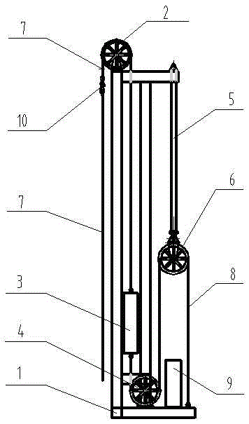
[0015] combined with figure 1 and 2 , to further describe the present invention:

[0016] A tension cylinder hydraulic pumping unit mentioned in the present invention includes a base and support assembly 1, an upper pulley assembly 2, a counterweight assembly 3, a lower pulley assembly 4, an oil cylinder assembly 5, and a movable pulley assembly 6 , working wire rope 7, power wire rope 8, hydraulic station assembly 9, rope hanger 10, described base and support assembly 1 are provided with upper pulley assembly 2, lower pulley assembly 4, oil cylinder assembly 5, power The installation support of the wire rope 8; the counterweight assembly 3 connects the working wire rope 7 and the power wire rope 8; the upper pulley assembly 2 is installed on the top of the base and the bracket assembly 1; the lower pulley assembly 4 is installed on the base and the bracket The lower part of the assembly 1; the upper end of the oil cylinder assembly 5 is installed on the top of the base and ...


PUM


Abstract

The invention relates to a hydraulic pumping unit with a tension-bearing oil cylinder and an application method. According to the technical scheme, the hydraulic pumping unit is characterized in that an upper pulley assembly is mounted at the top of a base and support assembly; a lower pulley assembly is mounted on the lower portion of the base and support assembly; the upper end of an oil cylinder assembly is mounted at the top of the base and support assembly; a movable pulley assembly is mounted at the lower end of the cylinder rod of the oil cylinder assembly; a counter weight assembly is located in the support of the base and support assembly and can move up and down; one end of a power steel wire rope is fixed on the base of the base and support assembly, and the other end thereof winds around the movable pulley assembly and the lower pulley assembly to be fixed on the lower portion of the counter weight assembly; one end of a working steel wire rope is connected with the upper portion of the counter weight assembly, and the other end thereof winds around the upper pulley assembly to be connected with a beam hanger. The hydraulic pumping unit has the advantages that the oil cylinder assembly is inverted, the cylinder rod only bears tension, and the oil cylinder is long in stroke, small in diameter and low in manufacturing cost; fixing supports of the working steel wire rope and the power steel wire rope are disposed on the counter weight assembly, the steel wire ropes are soft in transmission, and the pumping unit is small in noise, simple to mount, safe and environmental friendly.

Description

technical field [0001] The invention relates to an oil production machine used in the petroleum industry, in particular to a hydraulic oil pumping unit with a tension cylinder and a use method thereof. Background technique [0002] At present, there are many types of pumping units used in oil production in oil fields. Beam pumping units have many parts, heavy installation workload, low efficiency, complex equipment maintenance, high installed power, large energy consumption, large load changes, and short strokes. The chain pumping unit is noisy, and the stroke cannot be adjusted or is difficult to adjust; the forward and reverse motor pumping unit has a large starting current, low efficiency, and high cost; the hydraulic pumping unit or oil cylinder is thick or the system is complex, and the working conditions are bad; or the stroke is short, Expensive. Contents of the invention [0003] The purpose of the present invention is to solve the above-mentioned defects in the p...

Claims


Application Information

Patent Timeline
IPC IPC(8): E21B43/00F15B1/02F15B15/20
Inventor 李培江
Owner SHENGLI OIL FIELD XINDA PIPE IND TECH DEV CO LTD
Learn More