
Ultrasonic welding rack with stroke convenient to adjust

An ultrasonic welding, convenient technology, applied in the direction of welding equipment, welding equipment, auxiliary welding equipment, etc., can solve the problems of occupying factory space, difficulty in adjusting the height of the ultrasonic welding head, and low precision

Pending Publication Date: 2021-05-18
东莞市索莱德自动化科技有限公司
View PDF0 Cites 0 Cited by
  • Summary
  • Abstract
  • Description
  • Claims
  • Application Information

AI Technical Summary

Problems solved by technology

[0002] At present, the application of ultrasonic welding equipment is more and more widely, which is mainly used for welding metal, lithium battery leads, wire harnesses and electrical joints. Ultrasonic transducers and ultrasonic welding heads are the core components of ultrasonic welding equipment. When welding the parts to be welded, it is necessary to adjust the height of the ultrasonic welding head according to the needs. However, the adjustment mechanism for adjusting the height of the ultrasonic welding head in the current ultrasonic welding equipment has the disadvantage of low precision, that is, there is a shortcoming of the ultrasonic welding head. The shortcoming that the height is difficult to adjust in place; and the actuators of half-wave ultrasonic and full-wave ultrasonic in traditional ultrasonic welding equipment correspond to different welding frames, on the one hand, it increases the cost of purchasing ultrasonic welding equipment for enterprises, and on the other hand, the equipment needs to occupy the factory use of space

Method used


Image

  • Ultrasonic welding rack with stroke convenient to adjust
  • Ultrasonic welding rack with stroke convenient to adjust
  • Ultrasonic welding rack with stroke convenient to adjust

Examples


Embodiment Construction

[0030] The technical solutions in this embodiment of the present invention will be clearly and completely described below in conjunction with the accompanying drawings in this embodiment of the present invention. Obviously, the described embodiment is an embodiment of the present invention, not all This embodiment. Based on this implementation manner in the present invention, all other implementation manners obtained by persons of ordinary skill in the art without making creative efforts fall within the protection scope of the present invention.

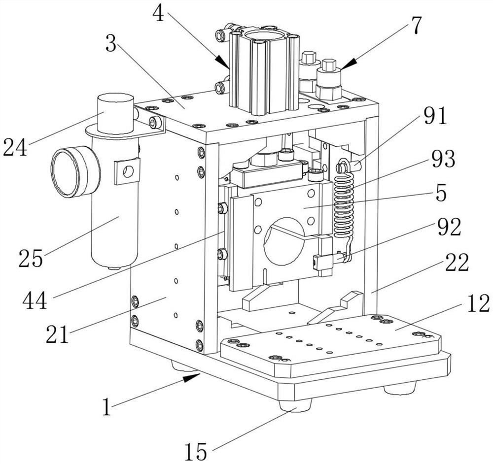
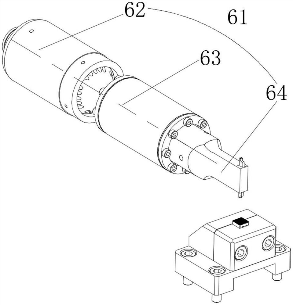
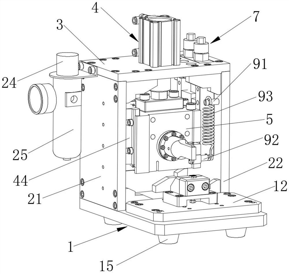
[0031] Please refer to Figure 1 to Figure 9, the present invention provides an ultrasonic welding frame with convenient stroke adjustment, including a base plate assembly 1, the front end of which is used to install a welding head base, and the rear end is used to install a welding device, and the base plate assembly 1 is a One side is equipped with a first support plate 21, and the other side is equipped with a second support plat...


PUM


Abstract

The invention discloses an ultrasonic welding rack with a stroke convenient to adjust. The rack comprises a bottom plate assembly, a first supporting plate is arranged at one side of the bottom plate assembly, a second supporting plate is arranged at the other side of the bottom plate assembly, a top plate is arranged at the top of the first supporting plate and the top of the second supporting plate, and a driving device is arranged on the top plate; and a hoop is movably connected to the lower portion of the driving device, the driving device drives the hoop to move up and down in a reciprocating manner, a welding executing assembly is arranged on the hoop, a limiting adjusting mechanism used for adjusting the stroke of the hoop is movably arranged at one side of the hoop, and the limiting adjusting mechanism is fixedly arranged at one side of the second supporting plate. According to the ultrasonic welding rack with the stroke convenient to adjust, the stroke of the welding head can be conveniently adjusted, welding parameters can be conveniently adjusted, executing mechanisms of half-wave ultrasonic waves and full-wave ultrasonic waves are compatible, exchange is easy, and space and cost are saved.

Description

technical field [0001] The invention relates to the technical field of ultrasonic welding equipment, in particular to an ultrasonic welding frame with convenient stroke adjustment. Background technique [0002] At present, the application of ultrasonic welding equipment is more and more widely, which is mainly used for welding metal, lithium battery leads, wire harnesses and electrical joints. Ultrasonic transducers and ultrasonic welding heads are the core components of ultrasonic welding equipment. When welding the parts to be welded, it is necessary to adjust the height of the ultrasonic welding head according to the needs. However, the adjustment mechanism for adjusting the height of the ultrasonic welding head in the current ultrasonic welding equipment has the disadvantage of low precision, that is, there is a shortcoming of the ultrasonic welding head. The shortcoming that the height is difficult to adjust in place; and the actuators of half-wave ultrasonic and full-w...

Claims


Application Information

Patent Timeline
IPC IPC(8): B23K20/10B23K20/26B23K37/02
CPCB23K20/10B23K20/26B23K37/02
Inventor 彭文燕戴海平
Owner 东莞市索莱德自动化科技有限公司
Learn More