Atomization dust removal device for refuse treatment station

A dust removal device and garbage disposal technology, applied in the field of environmental purification, can solve the problems of poor use effect, low efficiency of atomization nozzle, inability to completely cover dust removal and deodorization in the discharge room, etc., to achieve good atomization effect and good fog Optimize the effect of dust removal and realize the effect of intelligent operation

Active Publication Date: 2017-06-13
福建鑫骉科技有限公司
View PDF8 Cites 4 Cited by
  • Summary
  • Abstract
  • Description
  • Claims
  • Application Information

AI Technical Summary

Problems solved by technology

However, in the actual use process, the efficiency of the atomizing nozzle is not high, and it cannot completely cover the dust and deodorization of the entire discharge room, and the use effect is not good

Method used


Image

  • Atomization dust removal device for refuse treatment station
  • Atomization dust removal device for refuse treatment station
  • Atomization dust removal device for refuse treatment station

Examples


Embodiment 1

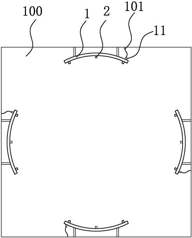
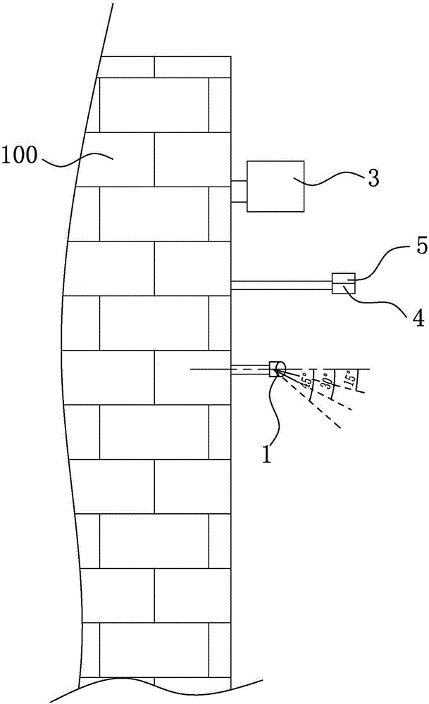
[0025] refer to figure 1 and figure 2 , an atomizing and dedusting device for a garbage disposal station, installed in the unloading room 100, which includes a water pump, atomizing equipment, and four atomizing nozzle mechanisms connected to the atomizing equipment and the water pump through pipelines 101, the atomizing The nozzle mechanisms are respectively installed on the four walls in the unloading room 100. The atomizing nozzle mechanism includes a nozzle 1 and three nozzles 2 arranged in the radial direction of the nozzle 1. The nozzle 1 is an arc-shaped tubular structure. One end of the spray pipe 1 is provided with a water inlet 11 connected to the water pump, and the inclination angles between the output direction of the nozzle 2 and the horizontal direction are respectively 15 degrees, 30 degrees, and 45 degrees horizontally downward, and each nozzle 2 is connected to the horizontal direction. The inclination angle increases evenly from the water inlet to the othe...

Embodiment 2

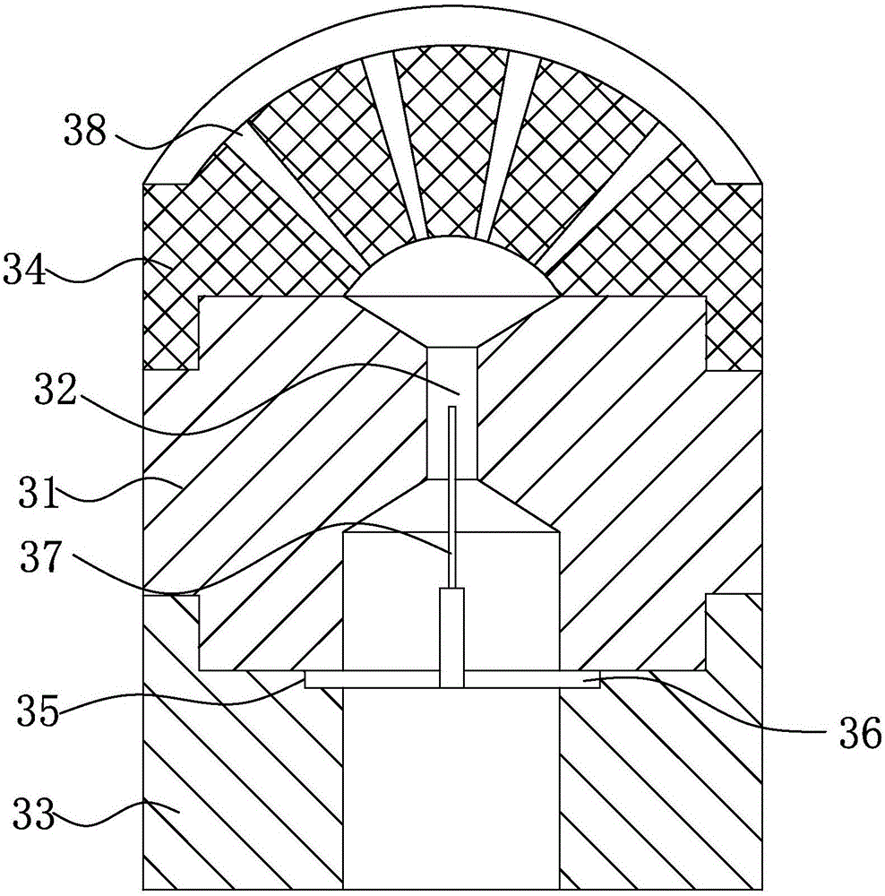
[0032] Such as Figure 4 , Figure 5 As shown, compared with the first embodiment, the parallel spray head 3 removes the step 35, the cross support frame 36 and the copper sheet 37, and a metal ring 39 is detachably clamped in the water flow channel 32. The metal ring The inner surface of 39 extends toward the center with eight baffles 391, the width direction of each baffle 391 is the same as the axis of the cluster block 31, and the thickness of each baffle 391 gradually increases from the water flow direction along the water flow channel 32, the The structure simplifies the structure of the original parallel nozzle 3 and improves the stability of the equipment.

[0033] In the present invention, the spray pipe 1 can also be connected to the atomization equipment, and the deodorant agent can be used for atomization and spraying.

[0034]This technical solution adopts the form of nozzles and multiple nozzles, which can ensure sufficient coverage area when the water is disch...


PUM


Abstract

The invention relates to the environmental purification field and particularly relates to an atomization dust removal device for a refuse treatment station. The atomization dust removal device comprises a water pump, atomization equipment and four atomizing nozzle mechanisms, wherein the four atomizing nozzle mechanisms are connected to the atomization equipment and the water pump through pipelines and are respectively mounted on four walls in a discharging room. The atomization dust removal device is characterized in that each atomizing nozzle mechanism comprises a spray pipe and a plurality of nozzles arranged on the radial direction of the spray pipe, wherein a water inlet connected with the atomization equipment or the water pump is formed in one end of the spray pipe, horizontal downward slant angles formed by the output directions of the spray nozzles and the horizontal direction are 15-45 degrees, and the slant angles formed by the output directions of the spray nozzles and the horizontal direction are different and uniformly increase from the water inlet to the other end of the spray pipe; and each atomizing nozzle mechanism comprises a parallel nozzle, and the parallel nozzle is arranged above the spray pipe and is connected with the atomization equipment.

Description

technical field [0001] The invention relates to the field of environmental purification, in particular to an atomizing dust removal device for a garbage treatment station. Background technique [0002] At present, the accumulative accumulation of urban garbage in the country has occupied more than 500 million square meters of land, and the annual economic loss is as high as 30 billion yuan. The cumulative accumulation of urban domestic garbage in the country has reached 7 billion tons. At the same time, with the development of the rural economy in recent years, the acceleration of urbanization, and the improvement of farmers' living standards, the output and accumulation of rural domestic waste are also increasing. It is estimated that the annual production of rural domestic waste has exceeded 200 million tons. At present, garbage transfer stations are often used for pretreatment of garbage, and a large amount of dust and odor will be generated during this treatment process,...

Claims


Application Information

Patent Timeline
Patent Type & Authority Applications(China)
IPC IPC(8): B01D47/06B01D53/00A61L9/14B08B15/04A61L101/56
CPCA61L9/14A61L2209/111B01D47/06B01D47/063B01D53/78B08B15/04
Inventor 邓金荣
Owner 福建鑫骉科技有限公司
Why Eureka
Try Eureka