
A low-floor rail vehicle underframe structure

A rail vehicle, low floor technology, applied in the direction of the chassis, railway car body parts, transportation and packaging, etc., can solve the problems of reducing internal space, physical contact, riding comfort and unsatisfactory vision, and achieve rational use of space. , Increase the vertical spacing, the effect of good running stability

Active Publication Date: 2017-10-03
ZHUZHOU ELECTRIC LOCOMOTIVE CO LTD
View PDF6 Cites 0 Cited by
  • Summary
  • Abstract
  • Description
  • Claims
  • Application Information

AI Technical Summary

Problems solved by technology

[0002] For low-floor trams at home and abroad, in order to realize the connection with the bogie, the aisle above the bogie is generally designed with steps or slopes, and the height of the floor is raised in the middle to meet the strength and rigidity requirements of the car body. Neither comfort nor visibility is ideal
[0003] In the low-floor car body of the prior art, the seats are arranged in horizontal rows facing each other, and the seating space is small, and there may be physical contact. Therefore, the lack of space in the tram is the biggest drawback
[0004] Moreover, the air spring installation surface of the low-floor tram in the prior art is low, resulting in a small vertical distance between the bogie and the car body, and a small space, which is not conducive to the arrangement of other devices.
The distance between the empty spring and the empty spring is small, and the stability is poor when supporting the car body

Method used


Image

  • A low-floor rail vehicle underframe structure
  • A low-floor rail vehicle underframe structure
  • A low-floor rail vehicle underframe structure

Examples


Embodiment Construction

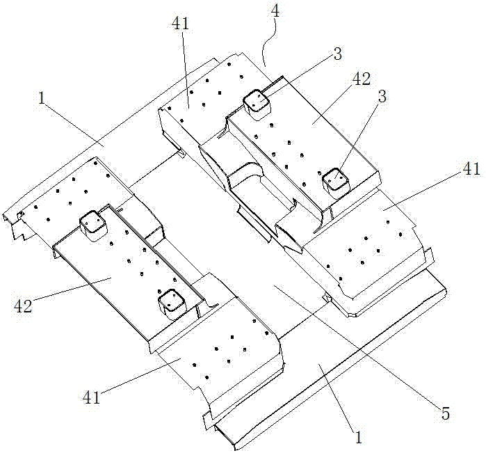
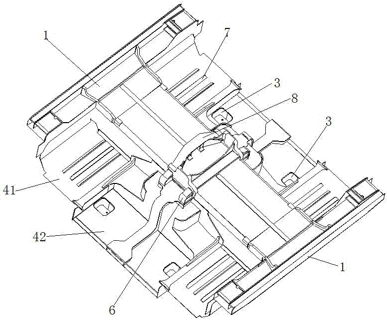
[0035] Such as Figure 1-8 As shown, a low-floor rail vehicle underframe structure includes end beams 1 respectively arranged at both ends, an aisle floor 5 is fixed in the middle of the end beams 1 at both ends, and side assemblies 4 are arranged on both sides of the aisle floor 5. The assembly is fixedly connected with the end beam 1. The side assembly 4 includes a transverse seat mounting plate 41 and a longitudinal seat mounting plate 42 higher than the transverse seat mounting plate 41 , the transverse seat mounting plate 41 and the longitudinal seat mounting plate 42 form a convex structure.

[0036] The aisle floor 5 is flush with other floors of the vehicle body.

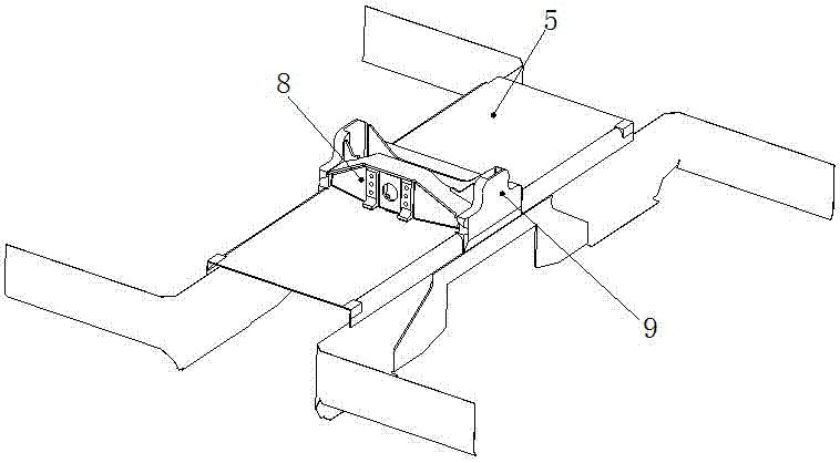
[0037] A traction seat 8 is provided on the back of the aisle floor 5 located at the longitudinal seat mounting plate 42, and a transverse stop 9 is provided on both sides of the traction seat 8, and a vertical stop 10 is vertically provided with the transverse stop 9. Both sides of the fifth wheel 8 and t...


PUM


Abstract

The invention discloses a chassis structure of a low-floor rail vehicle. The chassis structure comprises end beams arranged at the two ends respectively. An aisle floor is fixed between the end beams at the two ends. Side portion assemblies are arranged on the two sides of the aisle floor and are fixedly connected with the end beams. The side portion assemblies comprise transverse seat installation plates and longitudinal seat installation plates, wherein the longitudinal seat installation plates are higher than the transverse seat installation plates, and the transverse seat installation plates and the longitudinal seat installation plates form an inverted-T-shaped structure. The aisle floor is flush with other floors of a vehicle body. A traction seat is arranged at the back face of the part, located at the longitudinal seat installation plates, of the aisle floor. Transverse stopping blocks are arranged on the two sides of the traction seat, and perpendicular stopping blocks perpendicular to the transverse stopping blocks are arranged . Hollow perpendicular shock absorber installation seats are arranged on the front faces of the longitudinal seat installation plates in a protruding manner. According to the chassis structure of the low-floor rail vehicle, the non-step and slope-aisle structural design is adopted, the floor height does not need to be increased, and the low floors are ensured absolutely. Seats are longitudinally and transversely distributed, space arrangement is reasonable, and vehicle stability is good.

Description

technical field [0001] The invention belongs to rail vehicle body technology, and in particular relates to a low-floor rail vehicle chassis connection structure. Background technique [0002] For low-floor trams at home and abroad, in order to realize the connection with the bogie, the aisle above the bogie is generally designed with steps or slopes, and the height of the floor is raised in the middle to meet the strength and rigidity requirements of the car body. Neither comfort nor visibility are ideal. [0003] In the low-floor car body of the prior art, the seats are arranged in horizontal rows facing each other, and the seating space is small, and there may be physical contact. Therefore, the lack of space in the tram is the biggest drawback. [0004] Moreover, the low-floor tramcars of the prior art have a low mounting surface for the air springs, resulting in a small vertical distance between the bogie and the car body and a small space, which is unfavorable for the ...

Claims


Application Information

Patent Timeline
Patent Type & Authority Patents(China)
IPC IPC(8): B61F1/00
CPCB61F1/00
Inventor 罗宝陈赞平王锴岳译新刘永强王国军
Owner ZHUZHOU ELECTRIC LOCOMOTIVE CO LTD
Learn More