
Small lathe

A kind of lathe and small technology, applied in the direction of small lathes, lathes, etc., can solve the problems of complex structure, laborious clamping of parts, low efficiency, etc., and achieve the effect of improving rigidity and stability and reducing the moment of inertia

Inactive Publication Date: 2015-10-14
宁波神丰汽车部件有限公司
View PDF8 Cites 0 Cited by
  • Summary
  • Abstract
  • Description
  • Claims
  • Application Information

AI Technical Summary

Problems solved by technology

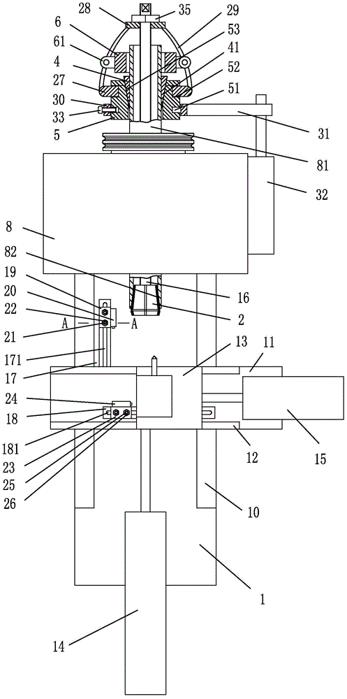
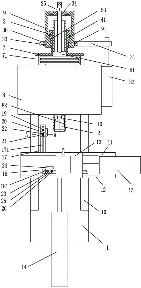
[0003] The purpose of the present invention is to overcome the disadvantages of complex structure, labor-intensive clamping and low efficiency of the current lathe components driven by motors and parts clamped by chucks, and to provide a simple structure and labor-saving and efficient clamping parts. Tall small lathes

Method used


Image

  • Small lathe
  • Small lathe
  • Small lathe

Examples


Embodiment 1

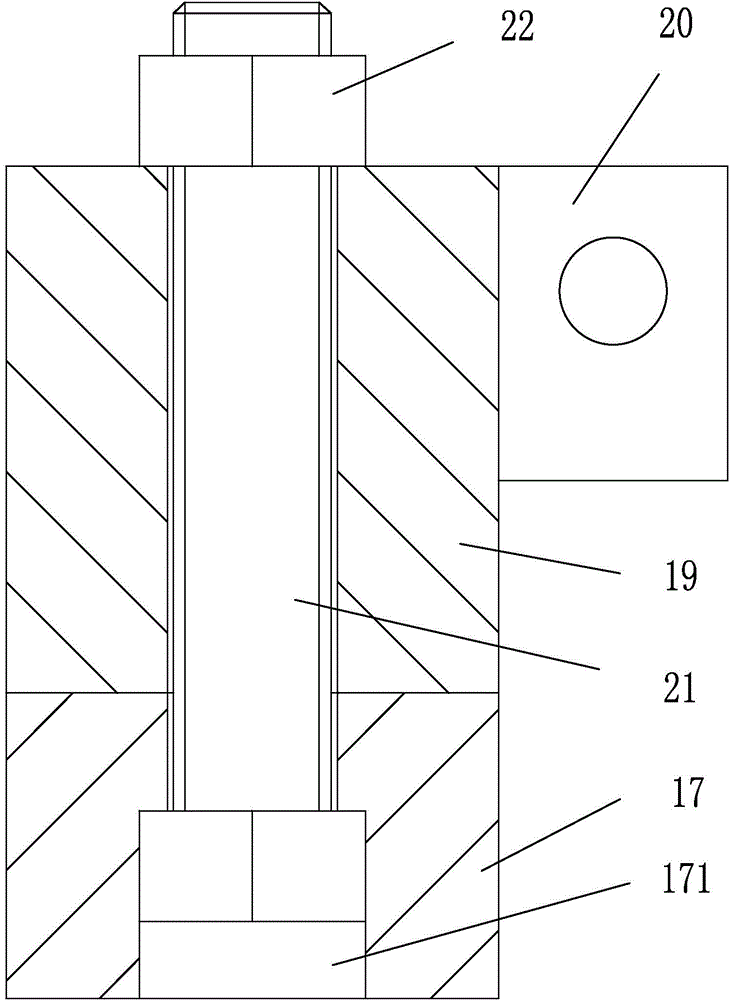
[0017] Embodiment 1, as attached figure 1 , attached image 3 Shown: a small lathe, including a bed 1, a headstock 8 with a spindle 81, a longitudinal carriage 11 connected to the bed 1 through a longitudinal guide rail 10, and a horizontal carriage 11 connected to the longitudinal carriage 11 through a transverse guide rail 12 Plate 13, the longitudinal cylinder 14 whose cylinder rod is screwed to the rear end of the longitudinal carriage 11 and screwed to the bed 1, the horizontal cylinder 15 whose cylinder rod is threaded to the rear end of the horizontal carriage 13 and screwed to the longitudinal carriage 11, The longitudinal limit assembly positioned at the front side of the longitudinal slide 11, the transverse limit assembly positioned at the front side of the horizontal slide 13, the tapered collet 2, the threaded connecting rod 16 and the connecting rod drive assembly; the front end of the main shaft 81 is provided with a cone The tapered hole 82 that the type colle...

Embodiment 2

[0023] Embodiment 2, as attached figure 2 , attached image 3Shown: a small lathe, including a bed 1, a headstock 8 with a spindle 81, a longitudinal carriage 11 connected to the bed 1 through a longitudinal guide rail 10, and a horizontal carriage 11 connected to the longitudinal carriage 11 through a transverse guide rail 12 Plate 13, the longitudinal cylinder 14 whose cylinder rod is screwed to the rear end of the longitudinal carriage 11 and screwed to the bed 1, the horizontal cylinder 15 whose cylinder rod is threaded to the rear end of the horizontal carriage 13 and screwed to the longitudinal carriage 11, The longitudinal limit assembly positioned at the front side of the longitudinal slide 11, the transverse limit assembly positioned at the front side of the horizontal slide 13, the tapered collet 2, the threaded connecting rod 16 and the connecting rod drive assembly; the front end of the main shaft 81 is provided with a cone The tapered hole 82 that the type colle...


PUM


Abstract

The invention relates to the field of machining equipment and provides a small lathe. The small lathe comprises a lathe bed, a spindle box provided with a spindle, a longitudinal dragging plate connected with the lathe bed through a longitudinal guide rail and a transverse dragging plate connected with the longitudinal dragging plate through a transverse guide rail. The small lathe further comprises a longitudinal cylinder, a transverse cylinder, a longitudinal limiting assembly, a transverse limiting assembly, a conical elastic clamp, a threaded connecting rod and a connecting rod driving assembly, wherein a cylinder rod of the longitudinal cylinder is connected with the rear end of the longitudinal dragging plate and is also connected with the lathe bed, a cylinder rod of the transverse cylinder is connected with the rear end of the transverse dragging plate and is also connected with the longitudinal dragging plate, the longitudinal limiting assembly is located on the front side of the longitudinal dragging plate, and the transverse limiting assembly is located on the front side of the transverse dragging plate. A conical hole matched with the conical elastic clamp is formed in the front end of the spindle. The front end of the threaded connecting rod penetrates through the spindle to be connected with the rear end of the conical elastic clamp in a threaded mode. The small lathe is simple in structure, capable of clamping parts effortlessly and high in efficiency.

Description

technical field [0001] The invention relates to the field of machining equipment, in particular to a small lathe. Background technique [0002] The structure of the small lathe can be understood from a kind of instrument lathe disclosed in the utility model of Chinese Patent Application No. 200620107461. Therefore, it is an urgent problem to design a small lathe with simple structure, labor-saving clamping parts and high efficiency. Contents of the invention [0003] The purpose of the present invention is to overcome the disadvantages of complex structure, labor-intensive clamping and low efficiency of the current lathe components driven by motors and parts clamped by chucks, and to provide a simple structure and labor-saving and efficient clamping parts. Taller small lathes. [0004] Concrete technical scheme of the present invention is: [0005] A small lathe, comprising a bed, a headstock with a main shaft, a longitudinal carriage connected to the bed through longit...

Claims


Application Information

Patent Timeline
Patent Type & Authority Applications(China)
IPC IPC(8): B23B3/02
CPCB23B3/02
Inventor 翁国畅徐文
Owner 宁波神丰汽车部件有限公司
Learn More