Anti-collision device for a robot

An anti-collision device and robot technology, applied in the field of robots, can solve the problems of immature technology and weak ability of robots to simulate reality, and achieve the effect of strong ability and strong implementability

Active Publication Date: 2020-08-25
南京斯杩克机器人技术有限公司
View PDF7 Cites 0 Cited by
  • Summary
  • Abstract
  • Description
  • Claims
  • Application Information

AI Technical Summary

Problems solved by technology

[0003] Most of the existing robots are equipped with buffers or some devices that withstand strong impacts when manufacturing robots, and cannot directly walk around obstacles in the process of walking, resulting in weak ability of the robot to simulate reality in terms of recognition and walking. , the technology is immature, so we propose a robot anti-collision device to solve the above-mentioned problems

Method used


Image

  • Anti-collision device for a robot
  • Anti-collision device for a robot
  • Anti-collision device for a robot

Examples


Embodiment 1

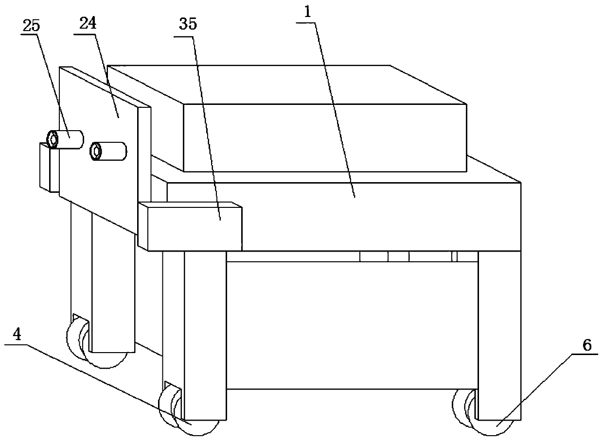
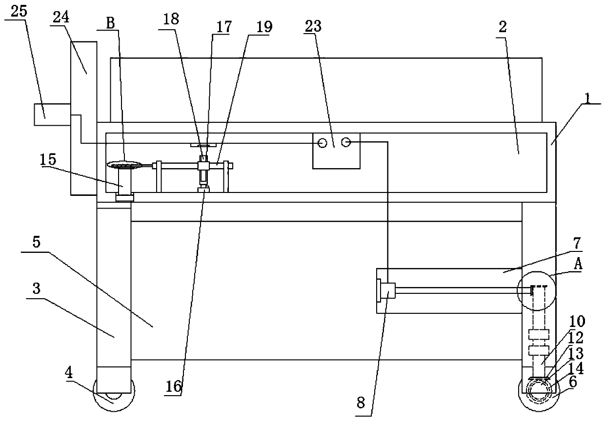
[0031] see Figure 1-6, this embodiment provides a robot anti-collision device, including a control block 1, a chamber 2 is arranged on the control block 1, four vertical rods 3 are mounted on the bottom of the control block 1, and two vertical rods on the same side The bottom of 3 is respectively provided with two steering wheels 4 and two driving wheels 6, and the side of four vertical rods 3 close to each other is fixedly installed with the same installation block 5, is provided with driving mechanism on the installation block 5, and two driving wheels 6 The side close to each other is provided with the same drive shaft 13, the drive shaft 13 is connected to the drive mechanism in transmission, and the tops of the two vertical rods 3 on the same side are fixedly installed with the steering shaft 15, and the top of the steering shaft 15 runs through the control block 1 and extends into the chamber 2, the interior of the chamber 2 is provided with a steering mechanism, and th...

Embodiment 2

[0035] see Figure 1-6 , further improvements have been made on the basis of Example 1:

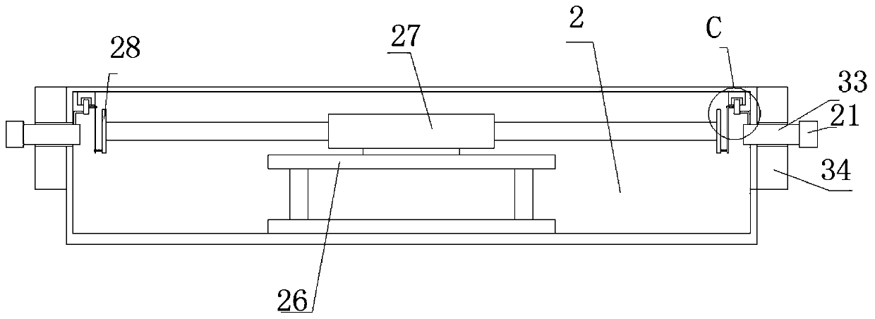
[0036] The sliding mechanism includes a cross bar 26 fixedly installed on the inner wall of the bottom of the chamber 2, a biaxial motor 27 is fixedly installed on the top of the cross bar 26, and a turntable 28 is fixedly installed on both output shafts of the biaxial motor 27, and the chamber 2 Two sliders 31 symmetrically arranged are slidably installed on the inner wall of the top of the top, and the two sliders 31 are respectively connected to the side of the two turntables 28 away from each other. The sides of the two sliders 31 away from each other are fixedly installed with L Shaped rods, the bottoms of the two L-shaped rods are fixedly connected to the tops of the two vertical bars 34 respectively, which can collect data on the obstacle situation at the steering position to avoid collisions;

[0037] An electric push rod 16 is fixedly installed on the bottom inner wall of the ch...


PUM


Abstract

The invention discloses a robot anti-collision device. The device comprises a controlling block, wherein the controlling block is provided with a chamber, four vertical rods are rotationally arrangedat the bottom of the controlling block, two steering wheels and two driving wheels are arranged at the bottoms of each two vertical rods on the same side, the sides, close to each other, of the four vertical rods are fixedly provided with the same mounting block, the mounting block is provided with a driving mechanism, the sides, close to each other, of two driving wheels are provided with the same driving shaft, the driving shaft is in transmission connection with the driving mechanism, and the tops of the two vertical rods on the same side are fixedly provided with steering shafts. Accordingto the robot anti-collision device, the information of the distance between the device and obstacles is fed back, the conditions of obstacles on the two sides of steering are fed back, a buffer device or certain devices capable of bearing strong impact force do not need to be arranged, the device can travel by bypassing the obstacles, the ability is strong in the case of obstacles of simulated reality, a new chapter is opened for subsequent research of robots, and the device is worthy of wide popularization.

Description

technical field [0001] The invention relates to the technical field related to robots, in particular to a robot anti-collision device. Background technique [0002] The first truly driverless cars appeared in the 1980s. In 1984, Carnegie Mellon University promoted the Navlab project and the ALV project. In 1987, Mercedes-Benz and the Federal Defense University in Munich jointly launched the Eureka Prometheus project. Since then, many large companies and research institutions have begun to build working prototypes of self-driving cars. Tesla Motors is the first to introduce self-driving cars in specific environments, and the concept of making robots is consistent with the concept of driverless cars. [0003] Most of the existing robots are equipped with buffers or some devices that withstand strong impacts when manufacturing robots, and cannot directly walk around obstacles in the process of walking, resulting in weak ability of the robot to simulate reality in terms of re...

Claims


Application Information

Patent Timeline
Patent Type & Authority Patents(China)
IPC IPC(8): B60W30/09B60W30/095B62D63/02B62D63/04
CPCB60W30/09B60W30/095B60W2420/40B62D63/02B62D63/04
Inventor 谢峻峰杨忠石致冰
Owner 南京斯杩克机器人技术有限公司
Why Eureka
Try Eureka