Air conditioner distributed air supply duct structure of shunting locomotive cab

A technology for shunting locomotives and driver's cabs, which is applied to the heating/cooling of locomotives, railway car body parts, and railway vehicles, and can solve the problems of high wind speed in the driver's cab, affecting the comfort of the driver's air conditioner, and high wind speed on the driver's head , to achieve the effect of avoiding high wind speed, preventing shutdown protection, and preventing wind speed from being too high

Pending Publication Date: 2019-12-20
CRRC ZIYANG CO LTD
View PDF0 Cites 1 Cited by
  • Summary
  • Abstract
  • Description
  • Claims
  • Application Information

AI Technical Summary

Problems solved by technology

[0002] In the existing shunting locomotives, the way of air supply for the air conditioner in the driver's cab is generally to set an air outlet grille on the top of the driver's cab to directly connect with the air outlet of the air conditioner. The wind speed on the driver's head is too high, which will affect the comfort of the driver's air conditioner

Method used


Image

  • Air conditioner distributed air supply duct structure of shunting locomotive cab
  • Air conditioner distributed air supply duct structure of shunting locomotive cab
  • Air conditioner distributed air supply duct structure of shunting locomotive cab

Examples


Embodiment 1

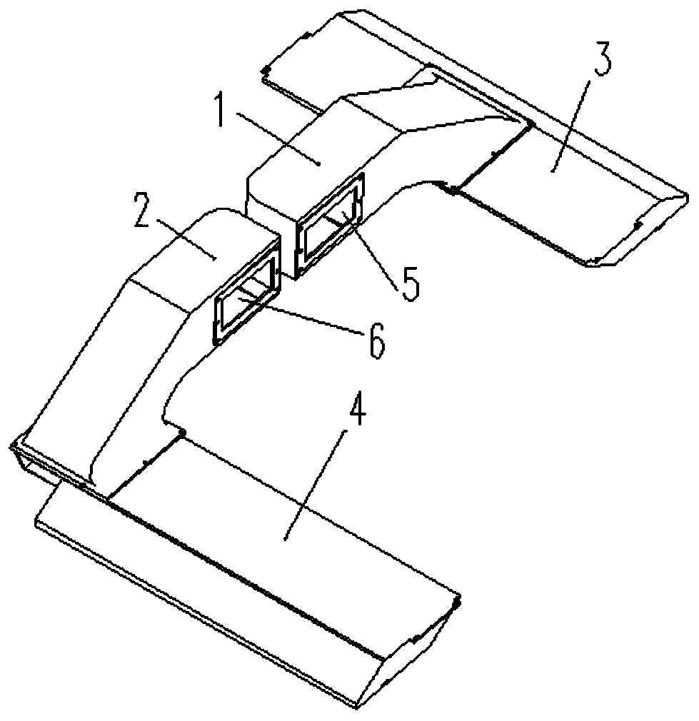
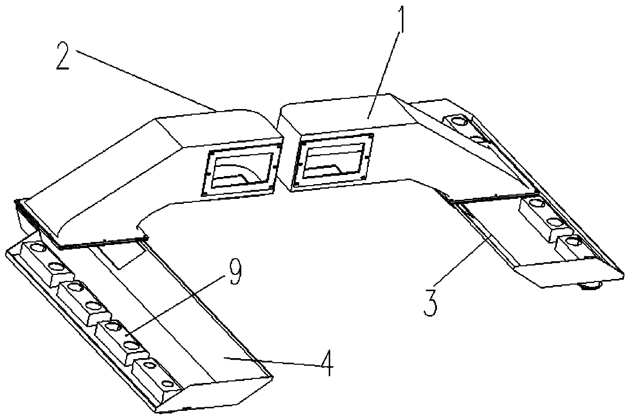
[0026] A distributed air-supply air duct structure for the cab of a shunting locomotive, such as Figure 1-3 As shown, it includes the upper left air duct 1 and the upper right air duct 2 placed on the top of the driver's cab, the upper left air duct 1 is provided with a butt hole 5 for the air outlet of the air conditioner, and the upper left air duct 1 and the upper left air duct 3 connected; the upper right air duct 2 is provided with a butt hole 6 of the air outlet of the air conditioner, and the upper right air duct 2 communicates with the right air duct 4; the bottom of the left air duct 3 and the bottom of the right air duct 4 are provided with A number of air outlets, the inside of the left air duct 3 and the inside of the right air duct 4 are provided with a static pressure partition chamber 9, one of the static pressure partition chambers 9 is arranged at 1-4 of the air outlets, and several of the air outlets There are several adjustable outlet grilles 7 placed at th...

Embodiment 2

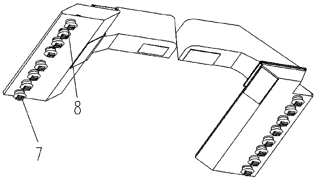
[0028] Based on the above-mentioned embodiment 1, such as figure 2 As shown, the bottom of the left air duct 3 and the bottom of the right air duct 4 are also provided with no less than two non-adjustable air outlet grilles 8 . In this embodiment, there are not less than two non-adjustable air outlet grilles 8 at the bottom of the left air duct 3 and the bottom of the right air duct 4 respectively, which can prevent the air conditioner from freezing and cause the air conditioner to shut down. This is because The air conditioner itself has a pressure alarm. After the evaporator tube freezes, the pressure inside the tube increases, and the alarm will shut down the air conditioner to protect the air conditioner. Therefore, if the air outlet grille is completely closed, the air circulation will be blocked, and the heat will not be exchanged. It will freeze, causing the air conditioner to be shut down for protection. Therefore, it is necessary to set the non-adjustable air outlet ...

Embodiment 3

[0030] Based on the above-mentioned embodiment 2, such as figure 2 As shown, the non-adjustable air grid 8 at the bottom of the left air duct 3 is set away from the upper left air duct 1 end, and the non-adjustable air grid 8 at the bottom of the right air duct 4 is far away from the upper right air duct 2 end. In this embodiment, the non-adjustable air grid 8 set on the left air duct 3 is kept away from the upper left air duct 1, and the non-adjustable air grid 8 set on the right air duct 4 is kept away from the upper right air duct 2, because the non-adjustable wind When the grid is away from the upper left air channel 1 and the upper right air channel 2, it is far away from the operator's seat console in the driver's cab, thereby ensuring that all the air outlet grids on the driver's seat are adjustable air grids 7.


PUM


Abstract

The invention discloses an air conditioner distributed air supply duct structure of a shunting locomotive cab, and the air conditioner distributed air supply duct structure comprises an upper left airduct and a right upper air duct which are placed on the top of a cab, a butt hole I of an air conditioner air outlet is formed in the upper left air duct, and the upper left air duct communicates with a left air duct; a butt hole II of the air conditioner air outlet is formed on the upper right air duct, and the upper right air duct communicates with a right air duct; a plurality of air outlets are provided at the bottoms of the left air duct and the right air duct, static pressure compartments are arranged in the left air duct and the right air duct, one static pressure compartment is arranged at 1-4 air outlets, a plurality of adjustable air outlet grills are arranged at the air outlets, and the adjustable air outlet grills are arranged at the bottoms of the left air duct and the rightair duct. The invention provides a distributed air supply duct structure, so a driver's comfort is improved effectively.

Description

technical field [0001] The invention belongs to the technical field of locomotives, and in particular relates to a distributed air supply duct structure for an air conditioner in a cab of a shunting locomotive. Background technique [0002] In the existing shunting locomotives, the way of air supply for the air conditioner in the driver's cab is generally to set an air outlet grille on the top of the driver's cab to directly connect with the air outlet of the air conditioner. The wind speed on the driver's head is too high, etc., which will affect the comfort of the driver's air conditioner. Contents of the invention [0003] The technical problem solved by the invention is to provide a distributed air supply duct structure, thereby effectively improving the driver's comfort. [0004] The technical scheme that the present invention adopts is as follows: [0005] A distributed air supply duct structure for air conditioners in shunting locomotive cabs, including an upper l...

Claims


Application Information

Patent Timeline
IPC IPC(8): B61C17/04B61D27/00
CPCB61C17/04B61D27/009
Inventor 吴振乾邓茂光栗绍毅张海洋姚尧王富强岳天军陈传彬王毅隆孝军
Owner CRRC ZIYANG CO LTD
Why Eureka
Try Eureka