Furnace slag split-flow heat exchange device

A heat exchange device and slag technology, which is applied in furnaces, waste heat treatment, furnace components, etc., can solve the problem of high wind speed in the area of ​​particles entering the hot air flue and air distribution board, and avoid excessive wind speed and high waste heat recovery and utilization efficiency. Effect

Pending Publication Date: 2018-03-16
中山蓝冰节能环保科技有限公司
View PDF0 Cites 0 Cited by
  • Summary
  • Abstract
  • Description
  • Claims
  • Application Information

AI Technical Summary

Problems solved by technology

[0005] In order to solve the problem in the prior art that when the wind quenching method is used to recover the waste heat of slag, the wind speed in the area of ​​the air distribution plate is too high, and the particles will be carr

Method used


Image

  • Furnace slag split-flow heat exchange device
  • Furnace slag split-flow heat exchange device
  • Furnace slag split-flow heat exchange device

Examples


Embodiment Construction

[0020] The present application will be further described below in conjunction with the accompanying drawings and specific embodiments.

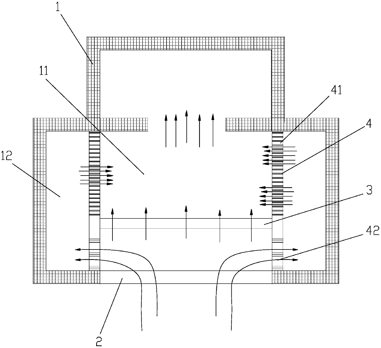
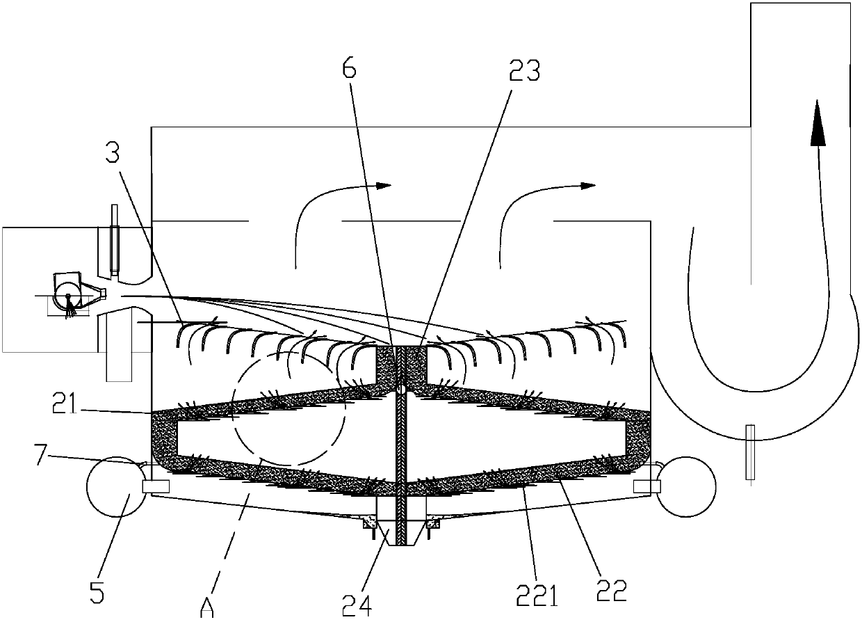
[0021] Such as Figure 1 to Figure 3 As shown, a slag shunt heat exchange device includes an airtight casing 1, and a slag collection chamber is arranged inside the airtight casing 1, and it is characterized in that a heat exchange material for carrying and transporting slag is arranged in the slag collection chamber. bed 2, an air distribution plate 3 is provided above the heat exchange material bed 2, the slag collection chamber includes a heat exchange chamber 11 located above the air distribution plate, and the inside of the side wall of the airtight casing 1 is provided with The distribution chamber 12, the upper end of the air distribution plate 3 is provided with a heat storage structure 4 for absorbing slag radiation heat, and the heat storage structure is provided with a channel 41 connecting the heat exchange chamber and the distrib...


PUM


Abstract

The application relates to a slag split flow heat exchange device, which includes an airtight casing. A slag collection chamber is arranged inside the airtight casing. A heat exchange material bed for carrying and transporting slag is arranged in the slag collection chamber. There is an air distribution plate, the slag collection chamber includes a heat exchange chamber located above the air distribution plate, a shunt cavity is provided on the inside of the side wall of the airtight shell, and a heat storage structure for absorbing slag radiation heat is provided at the upper end of the air distribution plate. Structurally, there is a channel connecting the heat exchange chamber and the distribution chamber, and the lower end of the air distribution plate is provided with an air hole connecting the slag collection chamber and the distribution chamber. The slag shunt heat exchange device of the present application can divert the airflow before entering the air distribution plate area to avoid excessive wind speed in the air distribution plate area; the heat storage structure at the top of the air distribution plate can be used to absorb radiant heat during slag granulation , the cooling air flow passing through the distribution cavity carries this part of the heat into the heat exchange cavity, and the recovery and utilization efficiency of waste heat is high.

Description

【Technical field】 [0001] The application relates to a slag split flow heat exchange device. 【Background technique】 [0002] At present, in the industrial field, smelting furnace equipment produces a large amount of slag during the production process. These slags are often accompanied by a large amount of waste heat. According to technical data, this part of waste heat resources accounts for more than 30% of its fuel consumption. It can be seen that the utilization of slag waste heat exists. Great potential. The utilization of waste heat from slag can not only reduce energy consumption per unit of product, but also reduce environmental pollution. Therefore, the utilization of waste heat from slag has considerable economic and social benefits. [0003] In the prior art, when the wind quenching method is used to recover the waste heat of the slag, there are the following disadvantages: 1. Due to the high wind speed in the area of ​​the air distribution plate, the particles wil...

Claims


Application Information

Patent Timeline
IPC IPC(8): F27D17/00
CPCF27D17/004F27D2017/007
Inventor 南建诚
Owner 中山蓝冰节能环保科技有限公司
Why Eureka
Try Eureka