A parachute system for aircraft recovery and landing recovery method

A recovery method and technology for an aircraft, applied in the field of parachute systems, can solve the problems of rocket landing impact, technical difficulty, and long cycle, and achieve the effects of horizontal recovery, maintaining stability, and avoiding overturning and winding.

Active Publication Date: 2021-03-23
北京凌空天行科技有限责任公司
View PDF5 Cites 2 Cited by
  • Summary
  • Abstract
  • Description
  • Claims
  • Application Information

AI Technical Summary

Problems solved by technology

[0002] At present, rockets and other aerospace vehicles are mostly used for one-time use, the cost remains high, and the launch cycle is long. Realizing the recovery of aircraft is an inevitable way to solve the high cost and long cycle
At present, there are mainly the following ways to realize the recovery of the aircraft: SpaceX’s Falcon 9 rocket reverses the thrust to slow down and deploys the landing legs to land smoothly. This recovery technology has high requirements for landing attitude control and greatly relies on the development of liquid engine technology. , the technology is very difficult and the cost is very high; the solid booster of the European Ariane-5 launch vehicle is recovered by parachuting, and its lifting point is located at the head of the booster, and it falls on the water in a vertical posture. The impact of landing is relatively large, which can easily cause damage to the structure of rockets and other aerospace vehicles

Method used


Image

  • A parachute system for aircraft recovery and landing recovery method
  • A parachute system for aircraft recovery and landing recovery method
  • A parachute system for aircraft recovery and landing recovery method

Examples


Embodiment 1

[0041] A parachute system for aircraft recovery, comprising a drogue parachute, a drogue sling, a drogue parachute front suspension point support, a drogue parachute rear suspension point support, a conversion sling, a drogue parachute rear suspension release bolt, a main parachute, and a main parachute Sling, main canopy front suspension point support, main canopy rear suspension point support, main canopy cover, main canopy cover unlocking bolt; figure 1 shown.

[0042] The suspension point support before the drogue parachute is installed on the main parachute hatch; the suspension point support after the drogue parachute is installed between the center of mass of the aircraft and the tail of the aircraft; the two ends of the drogue parachute hang respectively with The drogue parachute is connected to the rear suspension point support of the drogue parachute; the two ends of the conversion sling are respectively connected to the front suspension point support of the decelera...

Embodiment 2

[0047] A method for landing and recovering an aircraft, using the parachute system for aircraft recovery described in Embodiment 1, comprising the steps of:

[0048] S1. The drogue parachute goes out of the cabin, and the drogue parachute pulls the rear suspension point support of the drogue parachute through the drogue parachute belt to decelerate the aircraft; then turn to S2;

[0049] S2. After the aircraft decelerates to the preset main parachute opening speed, the deceleration parachute rear suspension point unlocking bolt separates the drogue parachute rear suspension support from the aircraft. Convert the sling to pull the front suspension point support of the drogue parachute to decelerate the aircraft; then turn to S3;

[0050] S3. When the angle of attack of the aircraft is greater than or equal to 35° or the angle between the conversion strap and the axis of the aircraft is greater than or equal to 35°, the main canopy canopy unlock bolt will separate the main canop...

Embodiment 3

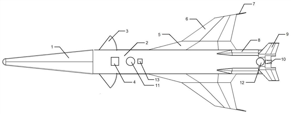
[0052] A deformable recovery aircraft, comprising a rocket body, canards 3, wings, air rudders 9, gas rudders 10, a parachute system, a thrust reverser engine system, and a landing gear system; figure 2 shown. The canard 3 is telescopically installed on both sides of the rocket body; the wings are installed on both sides of the rocket body; the air rudder 9 and the gas rudder 10 are all installed on the rocket body, Both are used for flight control; the parachute system is used for the deceleration of the aircraft in the subsonic section; the thrust reverser system is used for the deceleration of the aircraft before landing; the landing gear system is used for the landing of the aircraft .

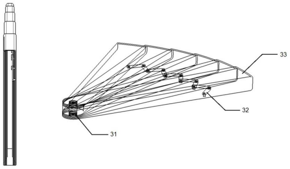
[0053] The canard 3 includes a motor-driven shaft 31, a folding link mechanism 32, and a plurality of wings 33; the plurality of wings 33 are connected through the folding link mechanism 32, that is, a plurality of wings 33 are stacked and set , the folding link mechanism 32 is installe...


PUM


Abstract

The invention relates to a parachute system for aircraft recovery and a parachute recovery method, and belongs to the technical field of rocket recovery. When a drag parachute is opened, a hanging point is positioned behind the mass center of an aircraft, so that the stability of the attitude of the aircraft is favorably kept, and the drag parachute is in close contact with the wall surface of a main parachute bay due to the large size of the main parachute; if the exit angle of a main parachute bag is smaller, the main parachute bag is easily clamped in a main parachute cabin to cause failureof opening the main parachute, so that the hanging point of the drag parachute is instantly switched to the front of the aircraft before the main parachute bag exits the cabin, the aircraft is liftedup, a certain angle is created for the exit of the main parachute bag, and smooth exit of the main parachute bag is realized; when the main parachute is opened, the opening force is larger, and if the aircraft with a single hanging point structure is adopted, the aircraft is easy to roll and is wound with a hanging belt of the main parachute, the parachute opening failure is caused, and the horizontal recovery is difficult to realize; and a front hanging point support of the main parachute is fixed in front of the center of mass, and a two rear hanging point supports are fixed behind the center of mass, so that the aircraft can be prevented from being overturned and wound when the main parachute is opened, and the horizontal recovery of the aircraft can be realized.

Description

technical field [0001] The invention relates to a parachute system for aircraft recovery and a landing recovery method, belonging to the technical field of aircraft recovery. Background technique [0002] At present, rockets and other aerospace vehicles are mostly used for one-time use, the cost remains high, and the launch cycle is long. Realizing the recovery of aircraft is an inevitable way to solve the high cost and long cycle. At present, there are mainly the following ways to realize the recovery of the aircraft: SpaceX’s Falcon 9 rocket reverses the thrust to slow down and deploys the landing legs to land smoothly. This recovery technology has high requirements for landing attitude control and greatly relies on the development of liquid engine technology. , the technology is very difficult and the cost is very high; the solid booster of the European Ariane-5 launch vehicle is recovered by parachuting, and its lifting point is located at the head of the booster, and it...

Claims


Application Information

Patent Timeline
Patent Type & Authority Patents(China)
IPC IPC(8): B64G1/62B64D17/54B64D17/64B64D17/70B64D17/32F42B10/58F42B15/00
CPCB64D17/32B64D17/54B64D17/64B64D17/70B64G1/62F42B10/58F42B15/00
Inventor 不公告发明人
Owner 北京凌空天行科技有限责任公司
Why Eureka
Try Eureka