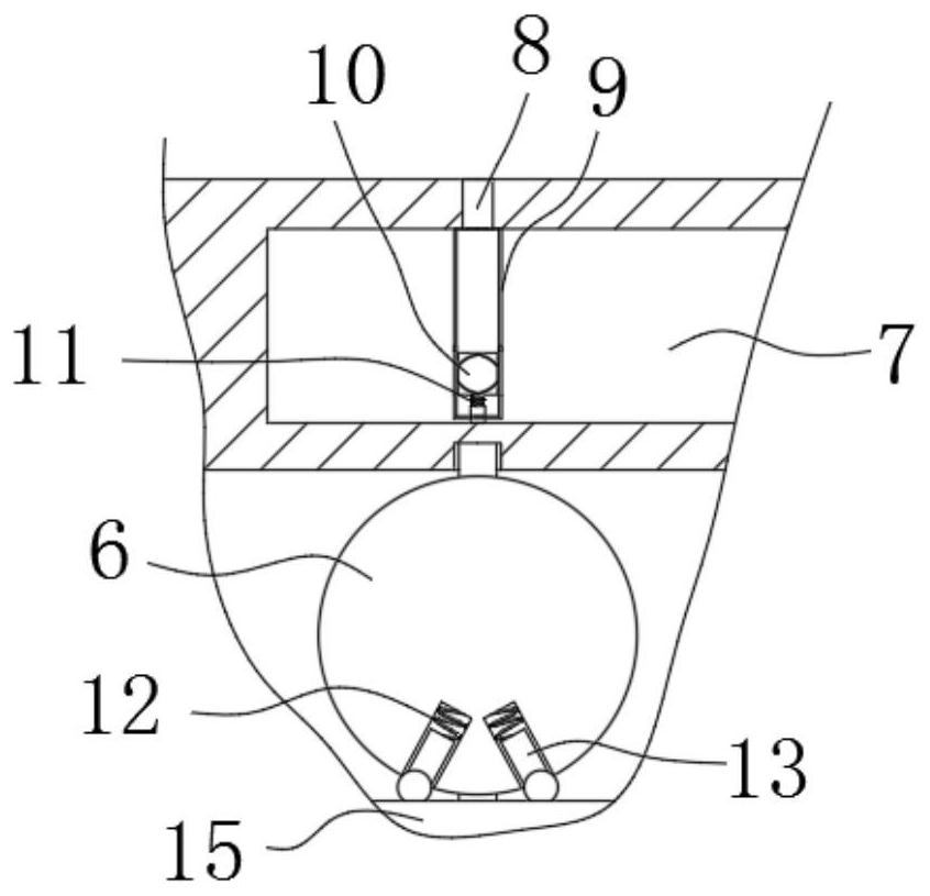
A deceleration system for traffic road construction

A deceleration system and road technology, applied in the direction of roads, roads, road signs, etc., can solve the problems of car body damage, road obstruction, and reduce the service life of cars, so as to reduce the risk of tire blowout, reduce losses, and reduce heat. Effect

Inactive Publication Date: 2021-08-27
张欣
View PDF5 Cites 0 Cited by
  • Summary
  • Abstract
  • Description
  • Claims
  • Application Information

AI Technical Summary

Problems solved by technology

[0003] However, the existing deceleration belt is an obstacle on the road. No matter whether the vehicle is speeding or not, it must pass through the deceleration belt, which will cause strong vibration to the vehicle body, which will bring irreversible damage to the vehicle body for a long time and reduce the service life of the vehicle.

Method used


Image

  • A deceleration system for traffic road construction
  • A deceleration system for traffic road construction
  • A deceleration system for traffic road construction

Examples


Embodiment Construction

[0019] The following will clearly and completely describe the technical solutions in the embodiments of the present invention with reference to the accompanying drawings in the embodiments of the present invention. Obviously, the described embodiments are only some of the embodiments of the present invention, not all of them.

[0020] In describing the present invention, it should be understood that the terms "center", "longitudinal", "transverse", "length", "width", "thickness", "upper", "lower", "front", " Orientation or position indicated by "back", "left", "right", "vertical", "horizontal", "top", "bottom", "inner", "outer", "clockwise", "counterclockwise", etc. The relationship is based on the orientation or positional relationship shown in the drawings, and is only for the convenience of describing the present invention and simplifying the description, rather than indicating or implying that the referred device or element must have a specific orientation, be constructed a...


PUM


Abstract

The invention discloses a deceleration system for traffic road construction, which comprises a groove set on the ground, and a speed-limiting plate arranged transversely is arranged in the groove, and the speed-limiting plate includes a fixed plate body and a rotating plate body. The rotating plate body is rotatably connected to the fixed plate body, and a first magnet set horizontally is installed on the rotating plate body, and a second magnet stone is fixedly connected in the groove, and an excitation magnet is wound around the second magnet body. coil. The invention can make the liquid in the cavity spray out from the nozzle in the form of mist through the interaction of the rotating disc, the limit pin, the limit groove and the pressure block, so that the road surface becomes wet, and the tire and the ground can be lowered. Between the heat, thereby playing a role in cooling, reducing the risk of blowout.

Description

technical field [0001] The invention relates to the technical field of traffic construction, in particular to a deceleration system for traffic road construction. Background technique [0002] With the development of society, automobiles have gradually become a means of transportation for human beings, which is derived from urban road planning. In the process of traffic road construction, vehicles need to travel at different speeds on different roads, so various roads are often seen on the road. A speed bump. [0003] However, the existing speed bumps form obstacles on the road. Regardless of whether the vehicle is speeding or not, it will pass through the speed bumps, causing the car body to vibrate strongly, causing irreversible damage to the car body for a long time and reducing the service life of the car. Contents of the invention [0004] The purpose of the present invention is to solve the shortcomings in the prior art, such as: the existing deceleration belts form...

Claims


Application Information

Patent Timeline
Patent Type & Authority Patents(China)
IPC IPC(8): E01F9/529E01H3/04
CPCE01H3/04E01F9/529
Inventor 张欣王非洲杨一威沈剑峰
Owner 张欣
Why Eureka
Try Eureka