Optical parts adjusting device

A technology for adjusting devices and parts, applied in the field of optical engineering, can solve the problems of inconvenient uniform discharge of sundries, inability to uniformly collect debris and other sundries and troubles, and achieve the effects of easy processing, convenient adjustment and good quality

Inactive Publication Date: 2019-12-20
扬州辰亚光学科技有限公司
View PDF4 Cites 2 Cited by
  • Summary
  • Abstract
  • Description
  • Claims
  • Application Information

AI Technical Summary

Problems solved by technology

The existing adjustment devices of this type cannot uniformly collect debris and other sundries generated during processing after the parts are processed, making it difficult to discharge the sundries uniformly, which is troublesome

Method used


Image

  • Optical parts adjusting device
  • Optical parts adjusting device
  • Optical parts adjusting device

Examples


Embodiment Construction

[0020] The following will clearly and completely describe the technical solutions in the embodiments of the present invention with reference to the accompanying drawings in the embodiments of the present invention. Obviously, the described embodiments are only some, not all, embodiments of the present invention. Based on the embodiments of the present invention, all other embodiments obtained by persons of ordinary skill in the art without making creative efforts belong to the protection scope of the present invention.

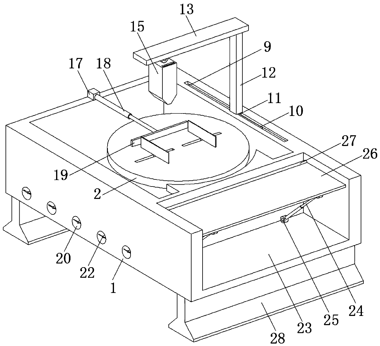
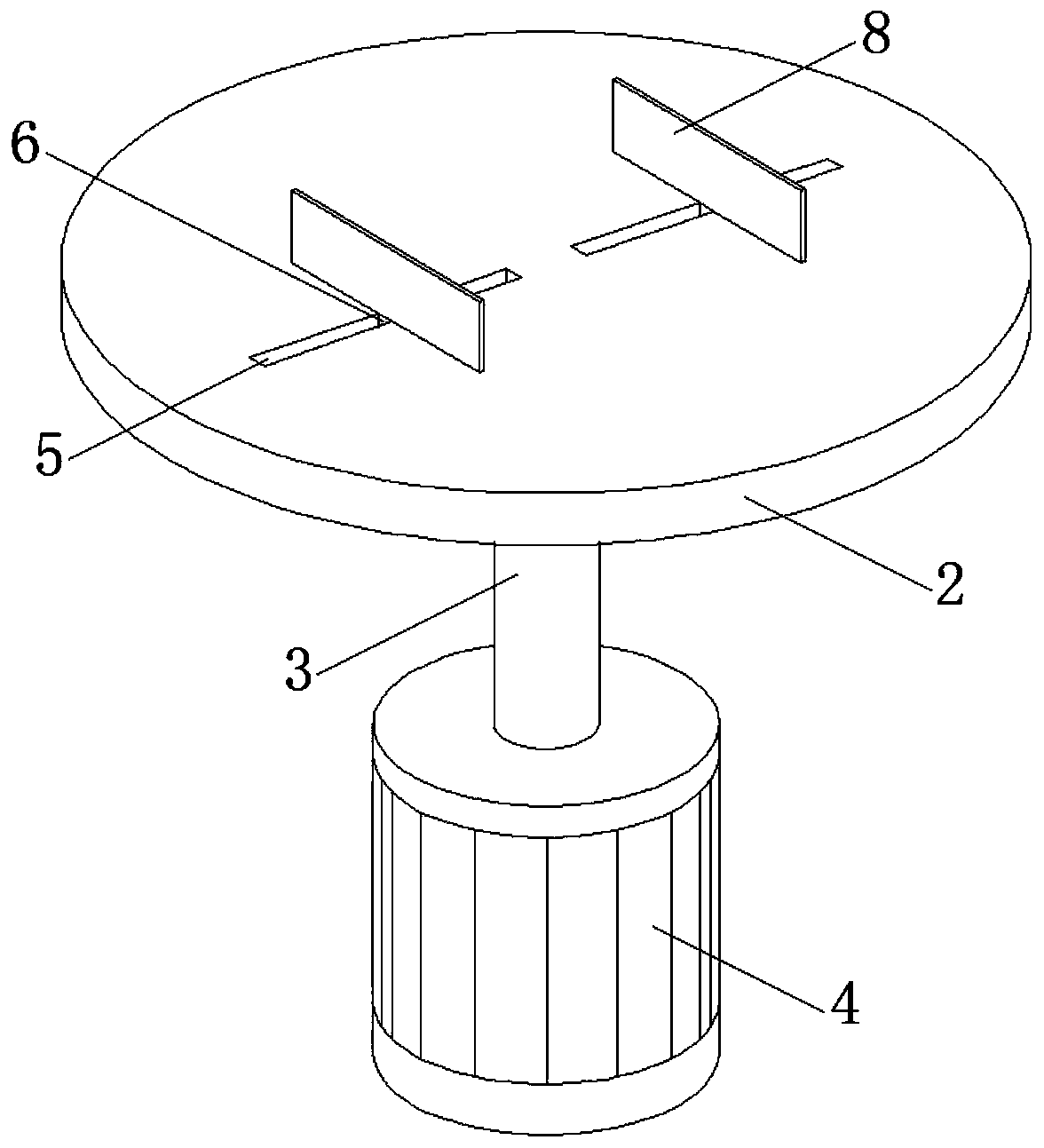
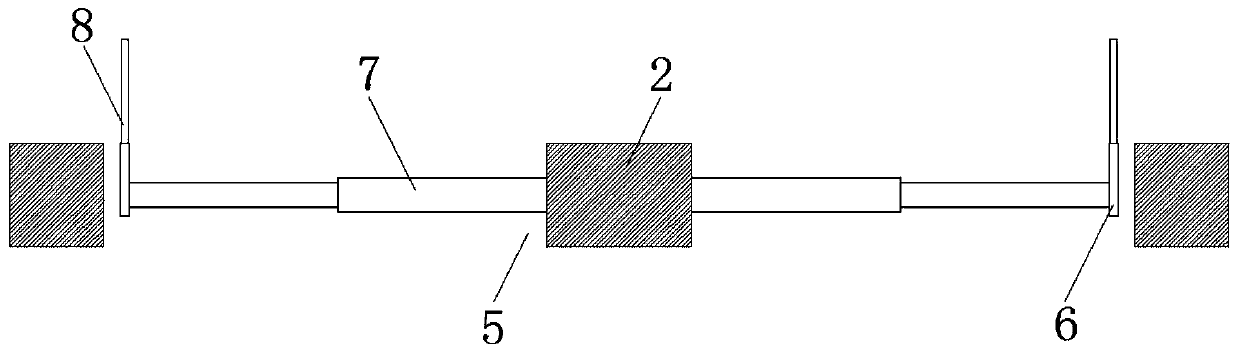
[0021] The present invention provides such Figure 1-5 The optical parts adjustment device shown includes a workbench 1 and an adjustment plate 2. The distance between the adjustment plate 2 and the side wall of the inner cavity of the workbench 1 should be as large as possible, so that debris can hardly be removed when the adjustment plate 2 is subsequently cleaned. Overflow to the outside of the workbench 1, the adjustment plate 2 is arranged in the inner ca...


PUM


Abstract

The invention discloses an optical parts adjusting device. The device comprises a worktable and an adjusting plate; the adjusting pate is arranged in an inner cavity of the worktable, a motor is fixedly welded at a bottom wall of the worktable, a driving shaft is arranged between a motor and the adjusting plate; two groups of mutually parallel moving slots are formed on a top wall of the adjustingplate, an adjusting block and a first telescopic rod are arranged in the inner cavity of each group of moving slots; two mutually parallel clamping plates are arranged on the adjusting plate; a sliding chute is formed at one side of the top wall of the worktable, and a stretching rod and a sliding block are arranged in the inner cavity of the sliding chute. By arranging the sliding chute, the stretching rod, the sliding block, an upright, a transverse plate, a direction-adjusting shaft, and a blower, a fan and the stretching rod in the blower can work simultaneously to drive the blower to blow the air to various locations on the surface of the adjusting plate, thereby conveniently feeding the scraps produced by machining the parts into the inner cavity of a machining table in a unified manner, and the scraps can be discharged subsequently in the unified manner.

Description

technical field [0001] The invention belongs to the technical field of optical engineering, and in particular relates to an optical component adjustment device. Background technique [0002] Optical engineering refers to a class of engineering that applies optical theory to practical applications. Optical engineering designs optical instruments, such as lenses, microscopes, and telescopes, as well as other devices that exploit the properties of optics. In addition, optical engineering also studies optical sensors and related measurement systems, lasers, optical fiber communications, and optical discs (such as CD, DVD), etc. [0003] The instruments of optical engineering are composed of precise parts, and these parts need to use related adjustment devices during processing. The existing adjustment devices of this type cannot uniformly collect debris and other sundries generated during processing after the parts are processed, making it difficult to uniformly discharge the ...

Claims


Application Information

Patent Timeline
Patent Type & Authority Applications(China)
IPC IPC(8): G02B7/00
CPCG02B7/00
Inventor 戚志洋
Owner 扬州辰亚光学科技有限公司
Why Eureka
Try Eureka