Street lamp pole base station
A street light pole and base station technology, which is applied in outdoor lighting, lighting and heating equipment, wireless communication, etc., can solve the problems of data transmission speed, base station coverage, narrow application range of light poles, and inability to adjust the height of light poles, etc., to achieve Improved coverage, improved lighting, and easy disassembly effects
- Summary
- Abstract
- Description
- Claims
- Application Information
AI Technical Summary
Problems solved by technology
Method used
Image
Examples
Embodiment 1
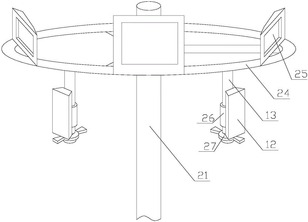
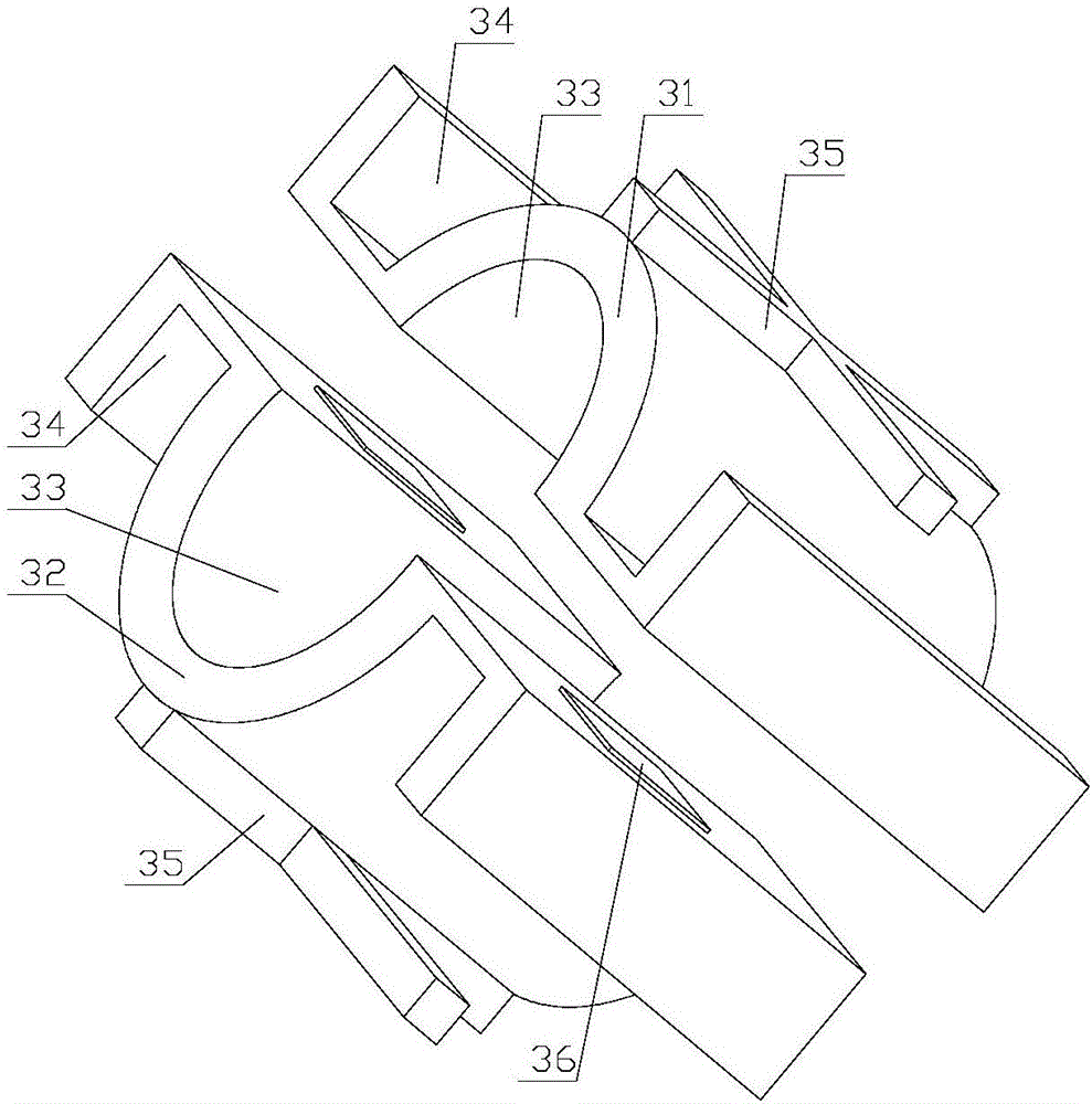
[0053] A lamp post base station includes a lamp post 21 installed on the roadside. A lamp panel 24 is connected to the top of the light pole 21 . The lamp panel 24 has a circular structure. The light pole 21 is formed by splicing the left cylinder piece 22 and the right cylinder piece 23. Since the light pole 21 is formed by splicing, the light pole 21 can be spliced into any length, thereby expanding its scope of application. The top of the lamp panel 24 is connected with an illuminating lamp 25, wherein multiple groups of the illuminating lamp 25 can be provided, and the multiple groups of illuminating lamps 25 are evenly distributed along the circumference of the lamp panel 24, so that multi-angle illumination can be realized. The base station connecting rod 13 is connected to the bottom of the lamp panel 24, and the base station connecting rod 13 is arranged vertically. The base station connecting rods 13 can be arranged in multiple groups, and the multiple groups of ba...
Embodiment 2
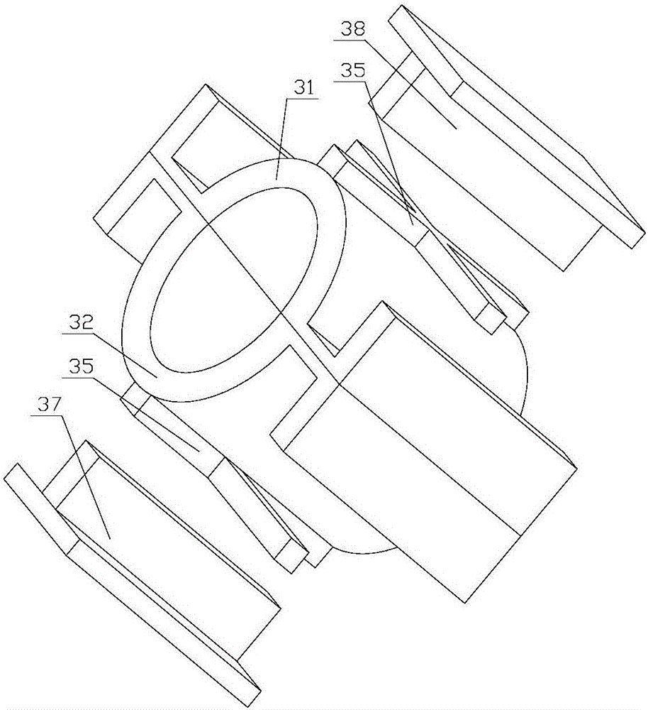
[0055]On the basis of Embodiment 1, a cross-shaped connecting block 35 is connected to the outer cylindrical surfaces of the left mounting body 32 and the right mounting body 31, and the cross-shaped connecting block 35 is connected to the left mounting body 32 and the right mounting body. The middle position of the outer cylindrical surface of 31. The left mounting flange 37 and the right mounting flange 38 are all connected with the cross-shaped connecting block 35 through a ball joint 39, so that the left mounting flange 37 and the right mounting flange 38 can rotate on the left mounting body 32 and the right mounting body 31 . As preferably, the left mounting flange 37 and the right mounting flange 38 are all provided with a sphere accommodation chamber for accommodating the ball head 39, at least 1 / 2 of the ball head 39 is located in the sphere accommodating chamber, and the remaining part emerges from the left side. The surface of mounting flange 37, right mounting flan...
Embodiment 3
[0057] On the basis of Embodiment 1, circular connecting plates are connected to the outer cylindrical surfaces of the left mounting body 32 and the right mounting body 31, and the circular connecting plates are all connected to the left mounting body 32 and the right mounting body 31. The middle position of the outer cylindrical surface. The outer contour of this circular connecting plate is all greater than the outer contour of left mounting flange 37, right mounting flange 38 and surrounds left mounting flange 37, right mounting flange 38; the outer contour edge of this circular connecting plate Scale lines are also provided, and several scale lines are arranged along the circumference of the circular connecting plate, and the rotation angles of the circular connecting plate and the base station 12 can be precisely controlled through the scale lines. The left mounting flange 37 and the right mounting flange 38 are all connected with the circular connecting plate through the...
PUM
 Abstract
Description
Claims
Application Information
 - R&D
- Intellectual Property
- Life Sciences
- Materials
- Tech Scout
- Unparalleled Data Quality
- Higher Quality Content
- 60% Fewer Hallucinations
Browse by: Latest US Patents, China's latest patents, Technical Efficacy Thesaurus, Application Domain, Technology Topic, Popular Technical Reports.
© 2025 PatSnap. All rights reserved.Legal|Privacy policy|Modern Slavery Act Transparency Statement|Sitemap|About US| Contact US: help@patsnap.com


