Barrel drum assembly, movement and timepiece
A technology of components and barrels, which is applied to clocks, movement sizes, mechanically driven clocks, etc., can solve problems such as decomposition and damage, and achieve the effect of inhibiting slippage and excellent maintainability
- Summary
- Abstract
- Description
- Claims
- Application Information
AI Technical Summary
Problems solved by technology
Method used
Image

Examples
no. 1 approach
[0048] Generally, a mechanical body including a driving part of a timepiece is called a "movement". The state in which the dial and hands are attached to the movement and put into the watch case to form a finished product is called the "finished product" of the watch. Of the two sides of the bottom plate constituting the base plate of the timepiece, the side where the glass of the timepiece case exists (that is, the side where the dial exists) is referred to as the "back side" of the movement. In addition, the side where the case back of the timepiece case exists (that is, the side opposite to the dial) among both sides of the bottom plate is referred to as the "front side" of the movement.
[0049] In addition, in the present embodiment, the direction from the dial to the case back cover will be described as the upper side, and the opposite side will be described as the lower side.
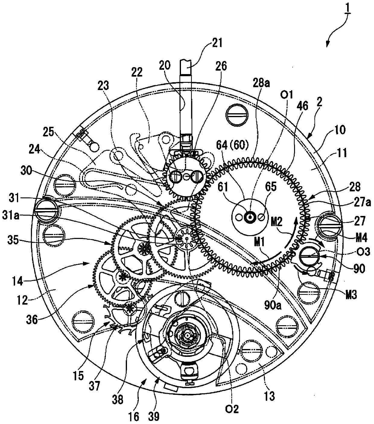
[0050] figure 1 It is a plan view of the movement of 1st Embodiment.
[0051] Such as fig...
no. 2 approach
[0095] Next, refer to Figure 4 A second embodiment will be described. In the first embodiment, the drum arbor 60 is screwed into the barrel arbor 50 . On the other hand, the second embodiment is different from the first embodiment in that the drum arbor 160 is pressed into the arbor 150 . In addition, structures other than those described below are the same as those of the first embodiment.
[0096] Figure 4 It is a sectional view of the barrel unit of the second embodiment.
[0097] Such as Figure 4 As shown, instead of the internal thread 51 of the arbor 50 of the first embodiment, a press-fit surface 151 into which the drum arbor 160 is press-fit is formed on the inner peripheral surface of the arbor 150 of the second embodiment. On the outer peripheral surface of the drum axle 160 of the second embodiment, a press-fit surface 163 into which the arbor 150 is pressed is formed to replace the external thread 63 of the drum axle 60 of the first embodiment. Thus, the d...
no. 3 approach
[0102] Next, refer to Figure 5 A third embodiment will be described. The third embodiment is different from the first embodiment in that a pin 273 is inserted into the through hole 165 of the flange 64 of the drum axle 160 . In addition, structures other than those described below are the same as those of the second embodiment.
[0103] Figure 5 It is a sectional view of the barrel unit of the third embodiment.
[0104] Such as Figure 5 As shown, a pin 273 protruding upward is provided on the large steel wheel 227 . The pin 273 is press-fitted into a pin insertion hole 274 formed in the drum 227 . In addition, the pin 273 may be press-fitted into a recess formed on the upper surface of the drum 227 . In addition, the pin 273 may also be integrally formed with the drum 227 . The pin 273 is inserted into the through hole 165 of the flange 64 of the drum shaft 160 from below. As a result, the drum 227 and the drum shaft 160 engage with each other in the circumferential...
PUM
 Abstract
Description
Claims
Application Information
 - R&D Engineer
- R&D Manager
- IP Professional
- Industry Leading Data Capabilities
- Powerful AI technology
- Patent DNA Extraction
Browse by: Latest US Patents, China's latest patents, Technical Efficacy Thesaurus, Application Domain, Technology Topic.
© 2024 PatSnap. All rights reserved.Legal|Privacy policy|Modern Slavery Act Transparency Statement|Sitemap