Drawer type mold frame

A mold frame and drawer-type technology, which is applied in the field of mold frames, can solve problems such as easy to crush and hurt people's hands and feet, no place to place, high cost, etc., to achieve enhanced support and fixation effects, enhanced fixation effects, and enhanced stability Effect

Pending Publication Date: 2019-12-24
苏州俊卿辉机械有限公司
View PDF0 Cites 0 Cited by
  • Summary
  • Abstract
  • Description
  • Claims
  • Application Information

AI Technical Summary

Problems solved by technology

[0002] Production, processing and manufacturing enterprises will use various types of molds. In the production workshop of the enterprise, the molds are often placed directly on the board or the floor without a fixed place. Not only is it messy, but it is also difficult to standardize the management of the molds. The molds have high precision. , Expensive features, if not properly preserved, the mold is vulnerable to man-made damage, and it is easy to crush people's hands and feet, resulting in work-related injuries. operation, making it more convenient to take and place the mold, therefore, further improvement is needed

Method used


Image

  • Drawer type mold frame
  • Drawer type mold frame
  • Drawer type mold frame

Examples


Embodiment 1

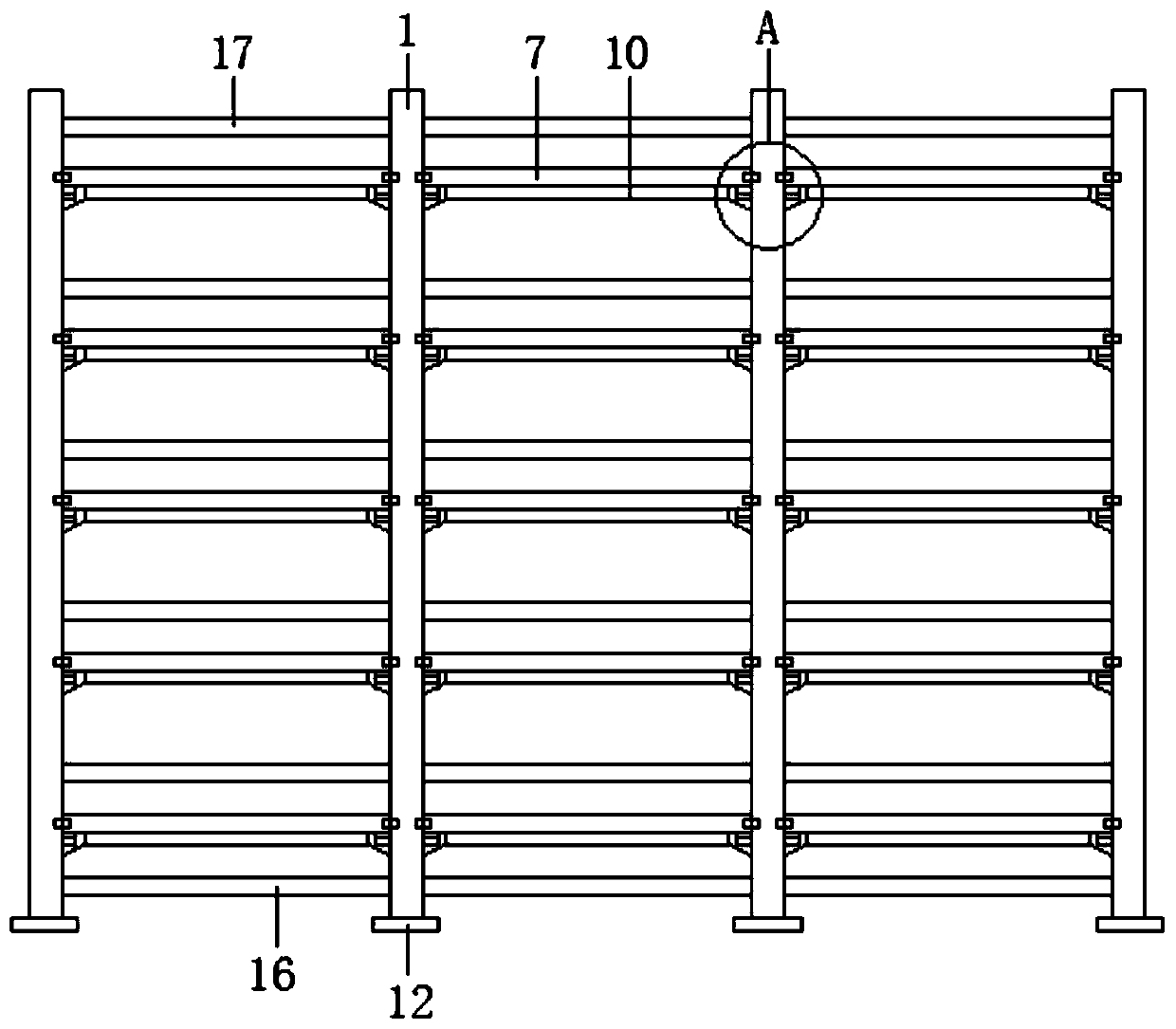
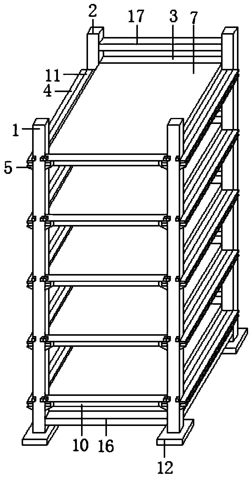
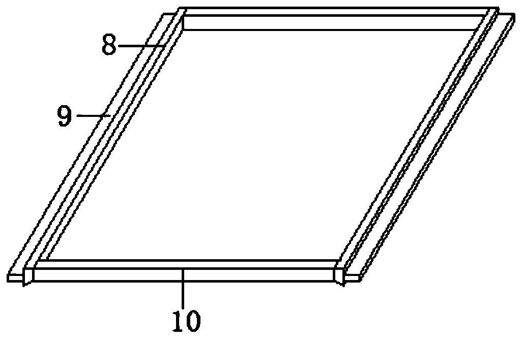
[0024] like Figure 1-5 As shown, a drawer type mold frame includes a first vertical bar 1 and a second vertical bar 2, the first vertical bar 1 is arranged on the front side of the second vertical bar 2, and the second vertical bar 2 is fixed The first fixing plate 3 is connected, which can not only strengthen the fixing effect on the second vertical bar 2, the upper sliding plate 4 and the lower sliding plate 5, but also block the horizontal plate 9 to prevent the horizontal plate 9 from being pushed into the sliding groove 6 too far. The two ends of the front side of the first fixed plate 3 are respectively fixedly connected with an upper sliding plate 4 and a lower sliding plate 5, and a sliding groove 6 is formed between the upper sliding plate 4 and the lower sliding plate 5, and the upper sliding plate The top of the plate 4 is provided with a placement plate 7 for placing the mould. The bottom of the placement plate 7 is fixedly connected with a connecting plate 8, and...

Embodiment 2

[0028] like figure 1 and figure 2 As shown, between the first vertical bar 1 and the second vertical bar 2, between the first vertical bar 1 and the first vertical bar 1, and between the second vertical bar 2 and the second vertical bar 2 are fixedly connected with The first reinforcing rod 16, and the first reinforcing rod 16 is close to the bottom of the first vertical rod 1 and the second vertical rod 2, to strengthen the stability between the first vertical rod 1 and the second vertical rod 2, the first The top of the fixed plate 3 is provided with a corresponding second reinforcing rod 17, and both ends of the second reinforcing rod 17 are fixedly connected with the second vertical rod 2, while strengthening the stability between the second vertical rods 2, Block the mold that is placed on top of plate 7.

[0029] The working principle of the present invention: when it is necessary to pull the placement plate 7 to facilitate the pick-and-place of the mould, operate the...


PUM


Abstract

The invention relates to a drawer type mold frame. The mold frame comprises a first vertical rod and second vertical rods, wherein the first vertical rod is arranged on the front sides of the second vertical rods, a first fixing plate is fixedly connected between the second vertical rods, the two ends of the front side of the first fixing plate are fixedly connected with upper sliding plates and lower sliding plates correspondingly, sliding grooves are formed between the upper sliding plates and the lower sliding plates correspondingly, a placing plate is arranged at the top of the upper sliding plates, connecting plates are fixedly connected to the bottom of the placing plate, the connecting plates are symmetrically arranged on the two sides of the placing plate correspondingly, transverse plates are fixedly connected to the one sides, which are not face to face, between the connecting plates correspondingly, the transverse plates are slidably connected in the sliding grooves correspondingly, and a second fixing plate is fixedly connected between the connecting plates. The mold frame is simple in structure and reasonable in design, and can effectively perform stable placing on a mold, and the mold can be more conveniently taken and placed by setting the placing plate as a drawing mode.

Description

technical field [0001] The invention relates to a drawer-type mold rack, which belongs to the technical field of mold racks. Background technique [0002] Production, processing and manufacturing enterprises will use various types of molds. In the production workshop of the enterprise, the molds are often placed directly on the board or the floor without a fixed place. Not only is it messy, but it is also difficult to standardize the management of the molds. The molds have high precision. , expensive features, if not properly preserved, the mold is vulnerable to man-made damage, and it is easy to crush people's hands and feet, resulting in work-related injuries. The operation makes the taking and placing of the mold more convenient, so further improvement is needed. SUMMARY OF THE INVENTION [0003] The purpose of the present invention is to provide a drawer-type mold rack, which can effectively and stably place the mold, and by setting the placement plate as a pull-out m...

Claims


Application Information

Patent Timeline
Patent Type & Authority Applications(China)
IPC IPC(8): B25H3/04
CPCB25H3/04
Inventor 朱仁川
Owner 苏州俊卿辉机械有限公司
Why Eureka
Try Eureka