Support structure of electric scooter
An electric scooter and support structure technology, which is applied in the directions of bicycle brackets, bicycle accessories, transportation and packaging, etc., can solve the problems of the support rod shaking up and down, potential safety hazards, and detachment.
- Summary
- Abstract
- Description
- Claims
- Application Information
AI Technical Summary
Problems solved by technology
Method used
Image
Examples
Embodiment 1
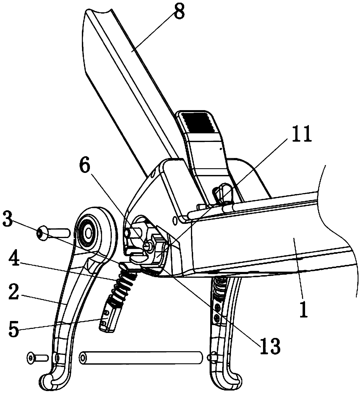
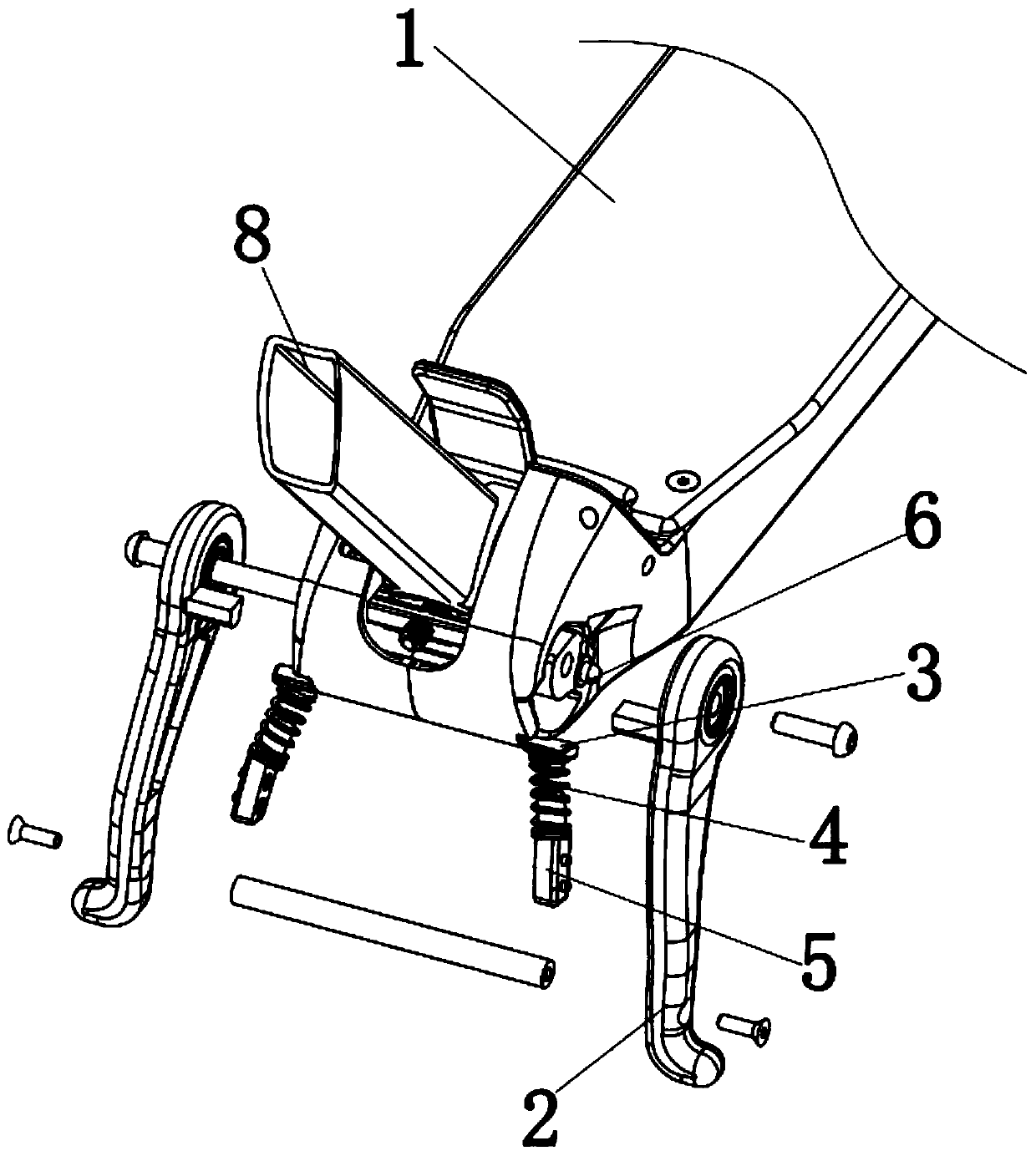
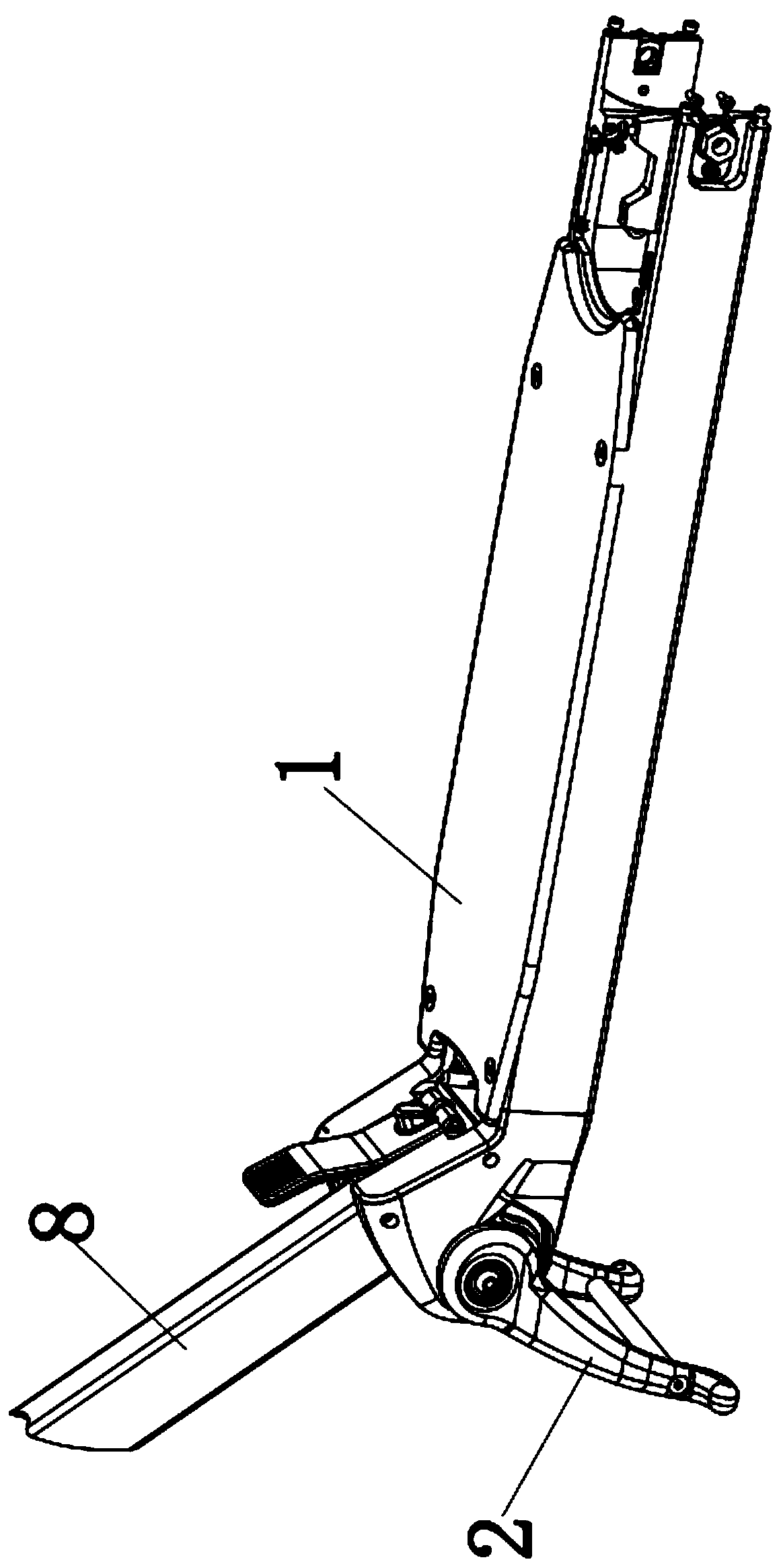
[0056] Such as figure 1 — Figure 11 As shown, a support structure of an electric scooter, comprising:
[0057] Skateboard 1, the side of the slideboard 1 is provided with a guide surface 11, the guide surface 11 is curved, the rear end of the guide surface 11 extends obliquely upward or upward, and the middle part of the guide surface 11 is provided with a corner;
[0058] A support frame 2, the upper end of the support frame 2 is rotationally connected with the skateboard 1, and the side of the support frame 2 close to the skateboard 1 is provided with a mounting groove 21;
[0059] An angle limiting component, the angle limiting component is installed on the support frame 2 or the slide plate 1, and is used to limit the rotation angle of the support frame 2;
[0060] The limit assembly, the limit assembly includes a block 3 and a first elastic member 4, the first elastic member 4 is installed in the installation groove 21, the block 3 is fitted on one end of the first ela...
Embodiment 2
[0071] Such as Figure 8 — Figure 12 As shown, in this embodiment, a connecting rod 8 and a limiting plate 9 are also included. One end of the connecting rod 8 is provided with a rotating connection part, which is connected to the slide plate 1 in rotation, and a third card slot is provided on the rotating connecting part. 81, the third card slot 81 is provided with at least two; the limit plate 9 is repositionably installed on the slide plate 1, and the end of the limit plate 9 is inserted into the third card slot 81, thereby limiting the rotation of the connecting rod 8; the guide The depth of the groove 23 changes gradually. When the support frame 2 is rotated, the limit rod 6 slides axially. Slide to one side of the limiting plate 9, and the limiting rod 6 is located in the moving direction of the limiting plate 9, and is used to limit the movement of the limiting plate 9. Specifically, the rotating connecting portion of the connecting rod 8 is in the shape of a round c...
PUM
 Abstract
Description
Claims
Application Information
 - R&D
- Intellectual Property
- Life Sciences
- Materials
- Tech Scout
- Unparalleled Data Quality
- Higher Quality Content
- 60% Fewer Hallucinations
Browse by: Latest US Patents, China's latest patents, Technical Efficacy Thesaurus, Application Domain, Technology Topic, Popular Technical Reports.
© 2025 PatSnap. All rights reserved.Legal|Privacy policy|Modern Slavery Act Transparency Statement|Sitemap|About US| Contact US: help@patsnap.com


