Vertical pumping anti-backflow controlling device and using method

A control device and anti-backflow technology, applied in the direction of control valves, valve devices, cleaning methods and appliances, etc., can solve problems such as blockage in the pipe and affect the pumping effect of the steel pipe column, and achieve the effect of easy unloading

Pending Publication Date: 2019-12-24
CHINA MCC17 GRP
View PDF0 Cites 2 Cited by
  • Summary
  • Abstract
  • Description
  • Claims
  • Application Information

AI Technical Summary

Problems solved by technology

In the existing equipment, when the pumping equipment stops pumping, the concrete in the pipe will form a negative pressure under the action of gravity

Method used


Image

  • Vertical pumping anti-backflow controlling device and using method
  • Vertical pumping anti-backflow controlling device and using method

Examples


Embodiment 1

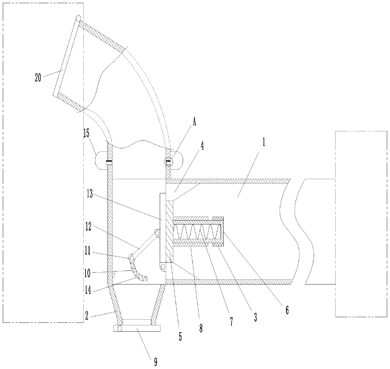
[0030] Such as figure 1 As shown, a vertical pumping anti-backflow control device is connected between the external pumping equipment and the steel pipe column, including the pumping pipe 1 and the transfer pipe 2, and the pumping pipe 1 is provided with an inlet and an outlet The feed port of the pumping pipe 1 is connected to the external pumping equipment. The pumping pipe 1 is provided with an anti-backflow structure, and the anti-backflow structure is used to prevent the concrete in the pipe from backflowing due to negative pressure when the pumping equipment stops. The anti-backflow structure includes a fixed seat 3, a guide seat 4 and a baffle plate 5. The fixed seat 3 is fixedly connected to the middle of the pumping pipe 1. The fixed seat 3 is fixedly connected with a fixed sleeve 6, and the fixed sleeve 6 is provided with a first spring 7. , the guide seat 4 is fixedly connected to the inner wall of the pumping pipe 1 and is located on the side of the fixed seat 3 cl...

Embodiment 2

[0032] Such as figure 1 As shown, the following improvements have been made on the basis of Embodiment 1. The transfer pipe 2 and the pumping pipe 1 are intersected. An isolation structure is provided in the transfer pipe 2. The isolation structure includes a chute 10, a sliding pin 11, a connecting rod 12 and Isolation plate 13, chute 10 is opened on the inner wall of transfer pipe 2, and second spring 14 is arranged in chute 10, and slide pin 11 is positioned at chute 10 and is connected with second spring 14, and one end of connecting rod 12 is connected with slide The pin 11 is rotatably connected, the other end of the connecting rod 12 is rotatably connected with the isolation plate 13, the isolation plate 13 is hingedly connected on the guide seat 4, and the isolation plate 13 is attached to the side wall of the baffle plate 5. When pumping, the baffle plate 5 pushes the isolation plate 13 to rotate so that the isolation plate 13 isolates the bottom of the transfer pipe ...

Embodiment 3

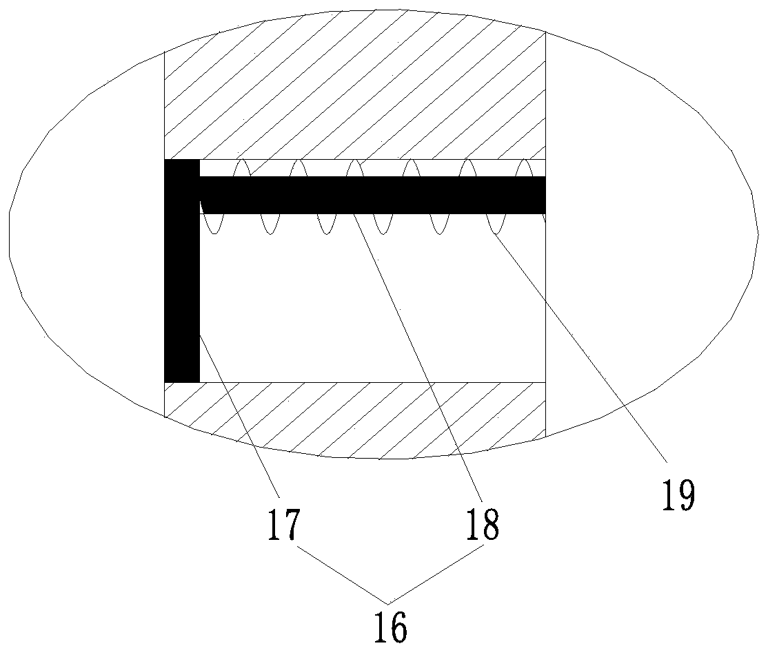
[0035] Such as figure 2As shown, the following improvements have been made on the basis of Embodiment 2. The adapter pipe 2 is provided with a flushing structure, and the flushing structure includes an annular flushing pipe 15. A pipeline is arranged between the annular flushing pipe 15 and the adapter pipe 2. An elastic water stop 16 is provided. The elastic water stopper 16 includes a disc part 17 and a connecting part 18, the disc part 17 is matched with the pipeline, the connecting part 18 is integrally connected with the disc part 17, the outside of the connecting part 18 is connected with a third spring 19, and the third spring 19 One end far away from the connecting portion 18 is connected with a pipe. By supplying water into the annular flushing pipe 15, the water pressure in the pipe is used to push the elastic water stop member 16 to move, and then the water in the pipe flows into the transfer pipe 2 to flush the inner wall of the transfer pipe 2 to prevent cloggin...


PUM

PropertyMeasurementUnit
Rotation angleaaaaaaaaaa

Abstract

The invention discloses a vertical pumping anti-backflow controlling device, and belongs to the field of concrete construction auxiliary devices. According to the device, an anti-backflow structure isarranged in a pumping pipe, the anti-backflow structure comprises a fixing seat, a guiding seat and a baffle, wherein the fixing seat is fixedly connected to the middle of the pumping pipe, a fixingsleeve is fixedly connected to the fixing seat, a first spring is arranged in the fixing sleeve, the guiding seat is fixedly connected to the inner wall of the pumping pipe, a through hole is formed in the middle of the guiding seat, the baffle is arranged in the through hole, a sleeve is fixedly connected to the baffle, the sleeve is movably connected to the outer side of the fixing sleeve, the baffle located in the sleeve is connected with the first spring located in the fixing sleeve, an adapter pipe is detachably connected to the discharging port of the pumping pipe and communicates with the pumping pipe, a door plate is hinged to the bottom of the adapter pipe, and the top of the adapter pipe extends into a steel pipe column. The device is reasonable in structure, convenient to use and safe and reliable, and it is guaranteed that after a vertical pump stops mechanical operation, the influence of backflow cannot be generated under the action of gravity.

Description

technical field [0001] The invention belongs to the technical field of concrete construction auxiliary devices, and in particular relates to a vertical pumping anti-backflow control device and a use method thereof. Background technique [0002] The pumping concrete technology mainly uses water pressure to make the concrete more and more dense, so as to continuously move the position and realize the delivery process of the slurry. In pumping concrete technology, with the rise of high-rise buildings, pumping technology has become a specialized technical field, among which ultra-high pumping concrete technology is the key core. In the existing equipment, when the pumping equipment stops pumping, the concrete in the pipe will form a negative pressure under the action of gravity and then the concrete in the pipe will flow back, which will cause blockage in the pipe in the long run and affect the pumping effect of the steel pipe column. Contents of the invention [0003] The pr...

Claims


Application Information

Patent Timeline
IPC IPC(8): F16K11/10F16K15/18B08B9/032E04G21/04
CPCB08B9/0321E04G21/04F16K11/105F16K15/1821
Inventor 徐华清王瀚
Owner CHINA MCC17 GRP
Why Eureka
Try Eureka