
Loading and unloading structure of refrigeration carriage

A car box and box body technology, which is applied in the field of refrigerated transportation, can solve the problems of expanding the horizontal space occupation of the car box, poor heat preservation effect, and increasing transportation costs, etc., to achieve the effect of ensuring safety and reliability, good positioning effect, and preventing loosening

Inactive Publication Date: 2016-03-23
CHONGQING SPEED COMPOSITE CO LTD
View PDF0 Cites 0 Cited by
  • Summary
  • Abstract
  • Description
  • Claims
  • Application Information

AI Technical Summary

Problems solved by technology

The outward-opening car door needs to be opened to one side or both sides of the car, so it will expand the occupation of the lateral space of the car, and the door cannot be fully opened in a narrow space, and it is not convenient to dock with a warehouse or other refrigerated cars in a narrow space. The goods need to be unloaded first and then loaded, which will easily melt the frozen items and spoil them; the inward-opening doors need to be opened to the interior of the carriage, so the goods in the carriage cannot be filled, resulting in waste of transportation space and increased transportation costs; Roller doors are thinner and less effective in heat preservation, and require a lot of power to cool in the refrigerated car during transportation, which increases transportation costs

Method used


Image

  • Loading and unloading structure of refrigeration carriage
  • Loading and unloading structure of refrigeration carriage
  • Loading and unloading structure of refrigeration carriage

Examples


Embodiment Construction

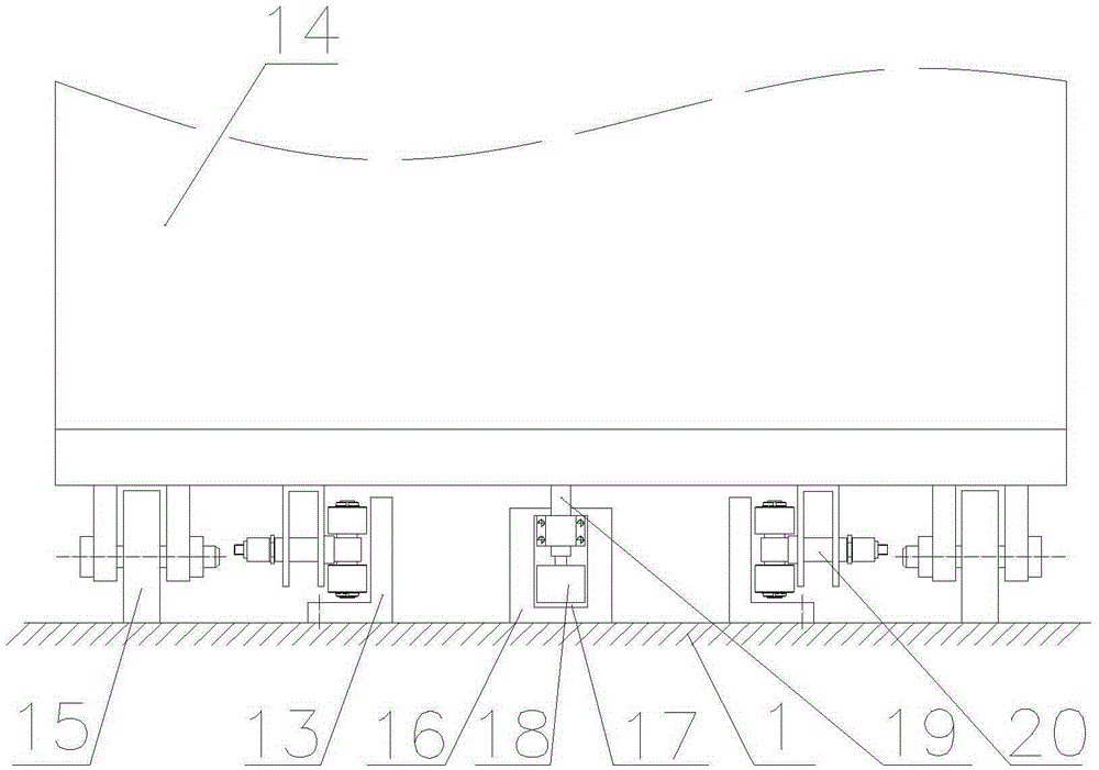
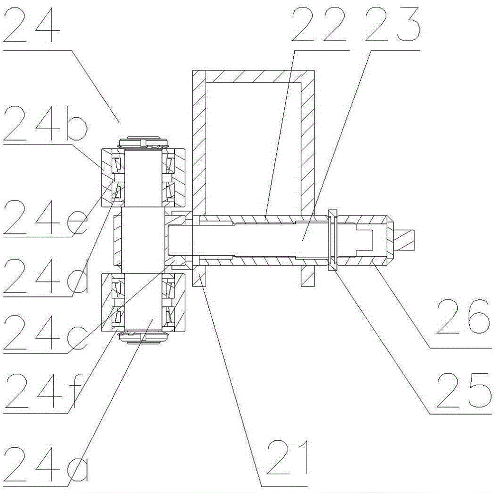
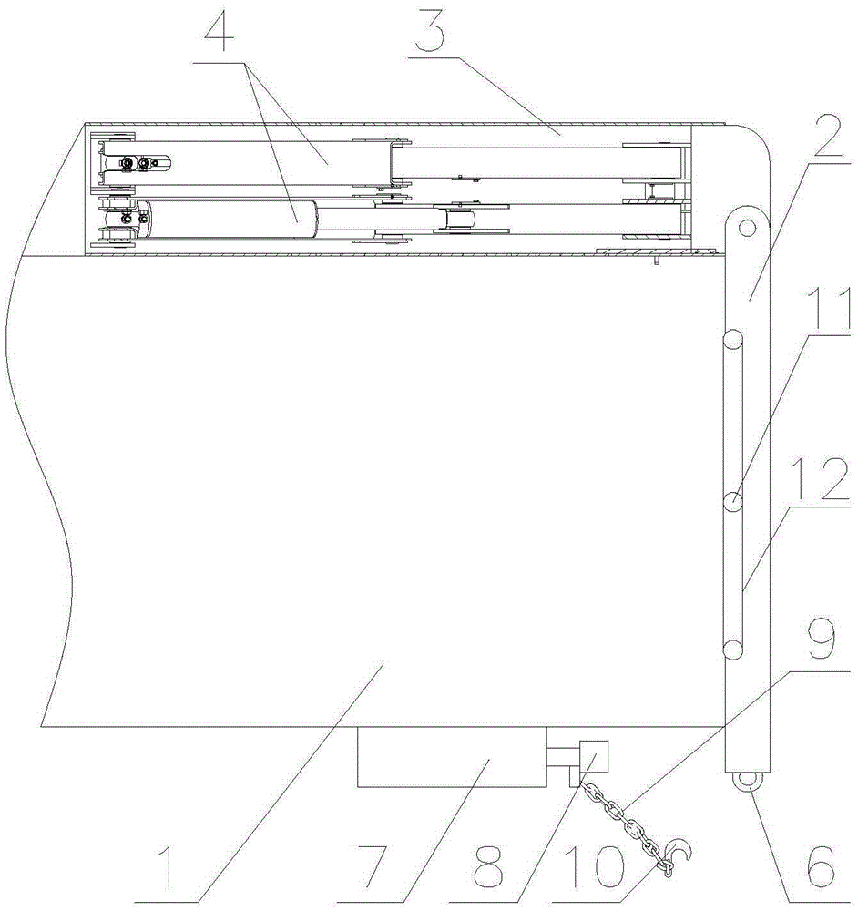
[0039] see figure 1 , figure 2 , is a preferred embodiment of the loading and unloading structure of the refrigerated truck box, including a box body 1, and one end of the box body 1 along the longitudinal direction is provided with a cargo inlet and outlet, and the box body 1 is provided with x pairs of boxes The track 13 extending longitudinally of the body 1, x≥2, the cross section of the track 13 is L-shaped, the vertical plates of each pair of track 13 are arranged oppositely, the flat plate of the track 13 is fixed on the bottom plate of the box body 1 by bolts, and also includes y 1 container 14, y≥x, y container 14 is divided into x groups, corresponding to x pairs of rails 13, two rows of supporting rollers 15 are arranged below the container 14, and the two rows of supporting rollers 15 are located on the corresponding two rails 13 The outer sides of each cargo box 14 are supported on the bottom plate of the box body 1 by supporting rollers 15, so that the cargo bo...


PUM


Abstract

The invention discloses a loading and unloading structure, facilitating loading and unloading, of a refrigeration carriage. The loading and unloading structure comprises a box body. One end, in the longitudinal direction, of the box body is provided with a goods feed-discharge opening. Rails extending in the longitudinal direction of the box body are arranged in the box body. The loading and unloading structure further comprises goods boxes corresponding to the rails. Support rolling wheels are arranged under the goods boxes. Two rows of limiting rolling wheel mechanisms are arranged under each goods box and located on the two sides of the corresponding rail. The loading and unloading structure further comprises pushing-puling air cylinders corresponding to the rails. The cylinder body ends of all the pushing-puling air cylinders are all located at the end, far away from the goods feed-discharge opening, of the box body. The piston rods of the pushing-puling air cylinders can extend out of the goods feed-discharge opening. Installation plates are fixed to the ends of the piston rods of all the pushing-puling air cylinders respectively. A locating air cylinder is fixed to each installation plate, and a piston rod of each locating air cylinder extends upwards. A locating rod is fixed to the end of each locating air cylinder piston rod. A guide sleeve used for guiding of the corresponding locating rod is fixed to each installation plate. The lower portions of the goods boxes are respectively provided with locating grooves corresponding to the locating rods.

Description

technical field [0001] The invention relates to the technical field of refrigerated transportation, in particular to a loading and unloading structure for a refrigerated car box. Background technique [0002] The cargo boxes in the existing refrigerated trucks are all directly placed in the trucks. The cargo boxes of this refrigerated truck need to be manually loaded and unloaded, which is very inconvenient to use. [0003] The car doors of existing refrigerated vehicles are all outward opening, inward opening or rolling shutter type. The outward-opening car door needs to be opened to one side or both sides of the car, so it will expand the occupation of the lateral space of the car, and the door cannot be fully opened in a narrow space, and it is not convenient to dock with a warehouse or other refrigerated cars in a narrow space. The goods need to be unloaded first and then loaded, which will easily melt the frozen items and spoil them; the inward-opening doors need to be...

Claims


Application Information

Patent Timeline
IPC IPC(8): B60P3/20B60P1/52
CPCB60P3/20B60P1/52
Inventor 徐开容李爽
Owner CHONGQING SPEED COMPOSITE CO LTD
Learn More